In a previous article we demonstrated how a single switch functions. One of the most frequent requests I receive is asking how the process would be different if there were multiple switches. This article will illustrate the process using two switches.
In the Packet Traveling series, we discussed the four specific functions of a switch: Learning, Flooding, Forwarding, and Filtering; we then illustrated each function in an animation that showed two hosts communicating through a single switch.
With multiple switches, each switch will still independently perform the exact same four functions. The process does not change, it is simply replicated separately by other switches.
We will illustrate how data moves between multiple switches using the following topology:
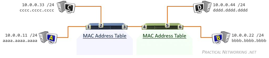
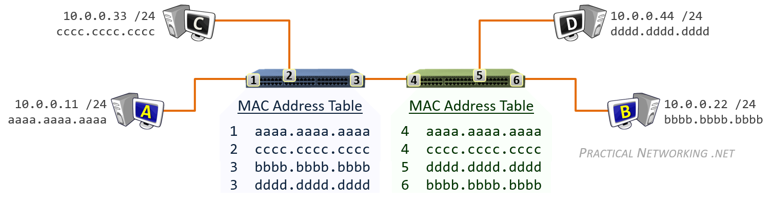
Our topology has two switches, and each has their own, independent MAC address table — the information in the MAC address tables are never shared.
Host A and C are connected to ports 1 and 2 of the blue switch on the left. Host B and D are connected to ports 5 and 6 of the green switch on the right. Port 3 on the blue switch is connected to port 4 on the green switch.
We will illustrate each step that occurs for each of the following:
- Initial frame from Host A to Host B
- Response from Host B to Host A
- Continued communication between Host A and Host B
Host A to Host B
It starts with Host A having a frame to deliver to Host B. The contents of the frame are irrelevant, it could be an ICMP (ping) packet, it could be an ARP packet, or it could be other data.
The Layer3 header would include a Source IP address of 10.0.0.11 (Host A) and a Destination IP address of 10.0.0.22 (Host B).
The Layer2 header would include a Source MAC address of aaaa.aaaa.aaaa and a Destination MAC address of bbbb.bbbb.bbbb. The switches will use the information in the Layer2 header to move the frame between the two hosts.
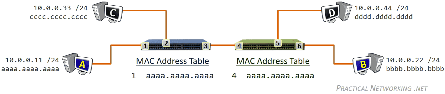
To begin, the MAC address tables for both switches will be empty. They will populate as the switches learn of each device connected to each port by reading the Source MAC address field of each received frame.
When the frame arrives on the blue switch, the first thing that happens is the blue switch learns the MAC address aaaa.aaaa.aaaa exists on port 1. Then, since the blue switch does not yet have an entry in tis MAC address table for bbbb.bbbb.bbbb, the frame is duplicated and flooded out every port.
The frame arrives on Host C, who will inspect the frame and realize it is not the intended recipient. Host C will silently discard the frame.
The frame will also arrive on the green switch. Just like the other switch, the first thing the green switch will do is learn that it received a frame on port 4 with a source MAC address of aaaa.aaaa.aaaa. And again, just like the other switch, the green switch does not know where the MAC address bbbb.bbbb.bbbb exists, so the frame will again be duplicated and flooded out each switch port.
Notice in both cases, the frame was flooded out each port, except the port it was received on. This is an example of a switch’s filtering behavior. This behavior prevents a switch from sending a frame out the same port it was received.
Host D will receive the frame, and silently discard it since the frame was not addressed to Host D.
Host B will receive the frame and accept it for processing, since Host B was the intended destination..
Host B to Host A
On the way back things will go a little simpler. The switches have already learned about some of the connected devices, and that should alleviate some of the additional flooding that was required for the initial communication in the previous section.
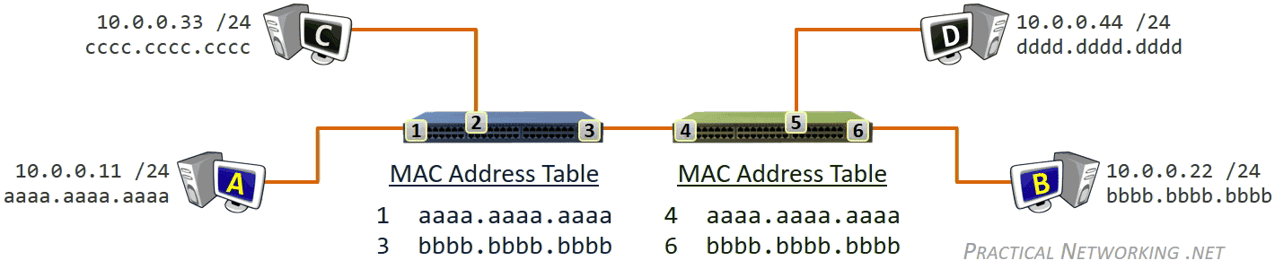
Specifically, both switches know the location of the MAC address aaaa.aaaa.aaaa – port 1 on the blue switch and port 4 on the green switch. Each switch learned the location independent of the other; there was no communication between the switches or sharing of MAC address tables.
In the response frame sent by Host B to Host A, the Layer2 header will have a Source MAC address of bbbb.bbbb.bbbb and a Destination MAC address of aaaa.aaaa.aaaa.
The response frame will first arrive on the green switch on port 6. Therefore, the green switch will learn that the MAC address bbbb.bbbb.bbbb exists out port 6. The green switch then consults its MAC address table to determine that the frame destined to aaaa.aaaa.aaaa should be forwarded out port 4.
The response frame then arrives on the blue switch on port 3. Therefore, the blue switch will learn the MAC address bbbb.bbbb.bbbb exists out port 3. The blue switch then consults its MAC address table to determine that the frame destined to aaaa.aaa.aaaa should be forwarded out port 1.
Which will finally get the response frame back to Host A. Notice on the way back no flooding was required. Both switches knew the location of the destination MAC address of the frame.
Communication with populated MAC Address Tables
Finally, with the both switches’ MAC address tables fully populated, communication between Host A and Host B resembles the following:
Each time a frame is received, the switch first attempts to learn the MAC address mapping on the receiving switch port. If the mapping is already known, it is simply refreshed in the MAC address table.
Notice, Host C and D receive none of the frames sent between Host A and B. The switch is able to create an isolated path for the data between these two hosts (so long as the MAC address tables remain populated).
This is one of the benefits of upgrading to a Switch from a simple Hub. With a Hub, every frame is flooded out every port, every time. Whereas with a switch (or a “smart hub”, as they are sometimes referred to) only the first few frames will be flooded, but all remaining communication between two hosts is confined to only those two hosts.
All Hosts
At some point in time, all hosts will have sent some frames, providing both switches the opportunity to learn the location of each MAC address in the topology above. At that point, the switch MAC address tables will resemble the image below:
The key item to note is that each switch port can learn of multiple MAC addresses. Notice, from the blue switch’s perspective, the location of Host B and D is out port 3. Moreover, from the green switch’s perspective, the location of host A and Host C is out port 4.
Full Process
Below is the entire process of Host A and Host B communicating, from beginning to end, and including the ability to pause/forward/rewind the animation. If you’ve read through this article and understand each step described above, you can use this animation to study. Or even better, to explain the process to someone else.


")
Your posts are inspiring! I really enjoy this blog and wish I came across it many years ago when I was doing my CCNA! I’m for sure adding it to my bookmarks!
Glad you enjoyed them, Neth3ro. Thanks for the kind words!
Hi Ed,
I am just ramping up on basic networking concepts.
I came across this website today and packet traversal article and it was very good to understand. Thanks for taking time to share your knowledge.
Planning to read the VLAN article next.
Can you please let me know if any write up or any details on L2 extension, LAG concepts?
Thanks,
Bala
Hi Bala, glad you enjoyed the articles! I hope you enjoy the VLAN articles as well (which are all available here: pracnet.net/vlans.
I don’t presently have articles in the pipeline regarding LAG and Etherchannels, but the best way to keep up to date is to sign up to get notified of udpates at the bottom of every page.
U rock buddy. U just solved all my doubts about how the data flows..
U r best in ur profession
Happy you enjoyed it, Ankit. Thanks for the read!
Hi
The article was much more informative than what I have ever read about switches before 🙂
But I am left with a single doubt about communication through multiple switches. Referencing above given terminologies, say blue switch has about 90 different devices connected excluding the green switch, same is the case with green switch.
Now each time data is communicated from blue switch to green switch or vice versa, mac address table of each switch will store only one mac address of the devices connected to other switch. Thus each time if destination mac address happen to be one of 89 devices of another switch whose mac address is not stored, the switch will end up flooding.
Thus at any point of time mac address table will store only one mac address of device connected to the other switch!
Is my understanding correct or do I need to add something else to it? Please let me know If I was unable to convey my thoughts as I am not as good as you are at this.
Hi Rajan,
You asked a great question. It is actually one I’ve gotten before, so I updated the article to speak to the situation.
To answer your question though, each switch port can learn of multiple MAC addresses. So the switch port connected to the other switch will learn all 90 devices exist out that port. Any traffic destined to those MAC addresses will only be forwarded out the appropriate port, not flooded.
Hope it helps.
Hey Ed Harmoush
Your posts are so simple to understand that it has made my many concepts clear. Thanks alot for that
I have a doubt or if you can make it clear it will be great help
This is more related to Virtual environment I understand packet will follow as below
VM1 > vSwtich > ESX1NIC > PSwtich > ESX2NIC > vSwtich > VM2
Both VM are in same Subnets and a single physical swtich is connected to both ESXi’s
VM1 packet will contain
VM1 Source MAC
VM1 Source IP
VM2 Destination IP
VM2 Source IP
Process of packet flow :
1. As the vswtich does not find entry in its MAC cache , it forwards the traffic to pSwtich
2. pSwtich will have MAC entry of the destination VM2 which will be mapped to the port of the ESX2NIC
3. pswtich will forward the traffic to vSwtich and vSwtich will lookup its MAC Cache and the forward the packet to destination VM2
Questions :
1. Is my above understanding correct ?
2. will Physical Swtich have MAC entry of multiple VM’s residing on vSwtich mapped to a single physical port ?
Hi Saurabh. Whether the switch is a virtual switch or physical switch it will operate the same — performing the same four switch functions: Learning, Flooding, Forwarding, and Filtering. Your topology of “VM1 > vSwtich > ESX1NIC > PSwtich > ESX2NIC > vSwtich > VM2” will work the same as if it were PC1 > Switch > Switch > Switch > PC2. In which case the same process as described in the article will occur. Hope this helps.
Thank u man very simple explain, easy to understand best with you a lot of luck
Ed,
Wow, you have a gift sir! Never have I seen such complex topics covered so clearly and simply. Well done!
I do have one question though. Let’s say that Host A has to get moved, for whatever reason, to port 7 on the blue switch. The blue switch still believes Host A is on port 1. How does the switch determine that the host has been moved and update it’s MAC table? From what I understand it doesn’t receive any confirmations once it’s routed the packet.
Many thanks
Steve
Hi Steve, glad you enjoyed the articles!
There are two answers that I think you are looking for.
The first, let’s say Host A moves from Port 1 to Port 7 on the blue switch. When the cable is disconnected, Port1 will transition to the down state, and that typically also causes any MAC addresses associated with that port to be purged. Next frame destined to AAAA will be flooded, and when Host A responds, the switch will learn the new location of Host A’s MAC address.
The second, let’s say Host A moves from Port 1 on the Blue switch to Port 8 on the green switch. The green switch had an entry in its MAC table that said the AAAA mac address existed out Port 4, and that interface never went down, so the entry was never purged. However, the first time Host A spoke on Port 8, the switch would learn the new mapping/location of the MAC address AAAA.
And lastly, since I think it is relative… MAC address tables time out, typically after 5 minutes of inactivity. So at worse, the incorrect mapping will exist for 5 minutes, before it is purged and the flooding/learning process learns the new mapping. Typically before that 5m is up, the host will send something, anything, into the switched network, which will update all the switches with the location of that host’s MAC address.
Hope this helps.
hello
thank you very much for explanation ,now all is clear for me
Hi.
I like the way you are explaining the concept.
I would like to ask do you have any Application of this tutorial in Play store.
Thanks.
Hi Sagar,
I’m happy you enjoy the content =).
I do not have any mobile apps, but the site is mobile responsive. It should be as effective in a mobile browser as it is on a desktop browser. Let me know if you find any bugs though!
Great series, thank you so much for it. I need to ask the following – in the first frame from host A to host B, why does host A know the destination IP and destination MAC already? I’m confused because both switches have to flood to learn it, yet the host already knows both of these pieces of information. I’m sure I’ve missed something obvious so would be grateful if you pointed it out.
Just reading around through other parts of your site – I believe you have simplified this for teaching purposes and actually the first frame from host A will be a broadcast with an incomplete layer 2 header?
Yes! Exactly. I wanted to focus on just the Switch behavior so I excluded the ARP process from the illustration. I wrote about ARP in another set of articles.
Hi ,
Thank you for the concepts explained here .I have a quick doubt , the first packet which goes out of the host would be an ARP packet right ? As , its ARP cache is empty .
so switch will flood the ARP request based on the L2 .
can you please clarify ?
Hi Karthik,
I wanted to write this article focusing solely on the switch actions (Learning, Flooding, Forwarding, and Filtering). So I left the host’s ARP resolution aspect out of the illustrations. If you want to see how it would work with ARP, check out the last article of the Packet Traveling series — it includes a video showing what every device will do (hosts, switches, and routers).
Nice article, Ed. Does a switch always flood a broadcast ARP packet? To scale it further. Does each switch in the network flood every broadcast ARP packet (in turn, each host in the network receiving the ARP request)?
Hi Govind. Yes, all switches will always flood a packet destined to
ffff.ffff.ffff. =)This might sound silly, will the switches need any trunk link to be able communicate between each other or it works just by connecting an Ethernet cable between the switch ports?
Switch’s don’t need trunk ports to communicate with each other. The Access or Trunk setting only indicates whether one or multiple VLANs can communicate on a link.
I have three queries. First is: A switch has many ports, do these ports have their own MAC addresses? Second: when there’s a broadcast frame to flood, does a switch first decide the method of forwarding n then flood? Third: u said every time when a switch receives a frame it checks d src MAC address, if it is already known it refreshes its Mac address table. What does it mean?
a. Yes, but they MAC addresses are not used for traffic going through the switch. Only if something was being sent to the switch (think STP or DTP, for example)
b.I’m not sure I understand. If a switch encounters a broadcast frame, it will always flood the frame.
c. The entries in the MAC address table are not permanent. They time after 5~ minutes of no activity. When a frame is received with a MAC address already in the MAC address table, the timeout is simply refreshed.
What my 2nd query is, is that a switch has 3 methods of forwarding a frame, right? So when it has to flood a broadcast frame, like ARP request, will switch use one of the 3 methods of forwarding to flood it. Store n forward, cut through or fragment free?
N I have to ask you on point C, if I’m creating a LAN with a Switch in it obviously, why would I unplug or plug d devices after every 5 mins, right? No one would do that, so y d people who standardized how a Switch should work would program it to keep refreshing its MAC table after every 5 mins? N what happens after 5 mins if it doesn’t receive a frame from a particular port? Does it delete that entry from its mac table?
Ahh, I see. The decision between Store and Forward, Cut Through, or Fragment Free is based upon the switch’s hardware and manufacturer — not something the switch chooses on a per-frame basis. The method of forwarding is separate from whether a switch will Forward or Flood.
As for your other question, despite there being limited movement, there is never no movement. Consider conference rooms or coffee shops, people come and go all the time, or move desks all the time. The network must have a way of adjusting as necessary. Furthermore (and this is outside the scope I intent to cover in this article), consider redundancy — sometimes there are two switching paths to a host, and only one can be active at any given time. Hence, the MAC address mapping must adjust to the active path.
Hi Ed,
I wanted to clarify something to make sure I understand correctly.
When host A is sending data to host B and it reaches the green switch, it does not know where bbbb.bbbb.bbbb is and floods the packet to all ports. Host B responds saying this is my MAC and receives the packet. Wouldn’t this add host B’s MAC address to the MAC address table of the green switch?
So in the subsequent communication from host B to A, the green switch would not have to learn the MAC address and would already have it in the MAC address table
You are correct. The illustration above is occurring as if ARP did not already occur. This was intentionally done to reduce the variables and just explain the switch’s role.
But the first part of the illustration would still apply if Host A’s first message was the ARP request. The only difference is the blue and green switch would be flooding because the ARP Request is a broadcast, and not because they do not know where the destination MAC address is.
More details here:
https://www.youtube.com/watch?v=G7GyWjJtjNs
Hello Ed, you are my life-saver. Thank you so much for this good article.
You’re welcome. Glad you enjoyed it.
This is the most practical and in-depth description of what happens when two switches are connected that I’ve ever read.
Excellent article, now my confusion is resolved.
Hi Ed, I have two questions if you can answer me. 1st QUESTION: Computer A communicating with computer on the same Switch. If “Computer A” wants to talk to “Computer C” the blue Switch will flood to everyone who is connected to the blue Switch, it even goes to port 3, and the green Switch will not let through to Computers “D” and ” B”?
2nd QUESTION: Blue Switch does not know the MAC of Computer B of the green Switch, but the green Switch has the MAC of Computer B in the table. Assuming that the blue Switch table is empty and the green Switch table already has the Computer MAC “B”. When Computer A sends a frame with destination MAC FF:FF:FF:FF:FF:FF that goes to all devices on the blue Switch and when the frame arrives on the green Switch the frame is forwarded directly to Computer B? If the green switch already knows where the MAC address bbbb.bbbb.bbbb exists, then of “Computer A” frame will not be flooded on each port of the green switch, even if the “Computer A” frame has the “L2 header” the destination MAC “FF:FF:FF:FF:FF:FF”?
Ask me on Discord, it would be easier than through wordpress comments: pracnet.net/discord
Can you tell how you was able to create the package to move across to the other pc . I need to create a presentation at work any I’m trying to show how things work at the access layer
The animation was done in Power Point.
You could also probably use the youtube videos for your presentation:
https://www.youtube.com/watch?v=AhOU2eOpmX0
https://www.youtube.com/watch?v=G7GyWjJtjNs
Hello Ed, if the communication were from Host A to Host C on the same Switch, if I understand correctly, when Host A does not have Host C’s mapping in the arp table and it sends an arp request with the destination MAC “FF: FF:FF:FF:FF:FF” this frame will also be flooded by all ports of the green Switch even if the destination is not a Host of the green Switch, because every frame with MAC of destination “FF:FF:FF:FF:FF :FF” is destined to be delivered to everyone on the local network? The same happens when using a Bridge connected to hubs, in the same scenario with Host A wanting to communicate with “Host C” only with “Hubs” and a Bridge, the “frame” with the destination MAC “FF:FF:FF:FF :FF:FF” would also pass across the Bridge to another network segment. The “frame” only would not pass to the other segment of the network if “it” had in the “package” the destination MAC of the “Host C” of the same Hub. Is my understanding correct about the two examples?
I think we answered your question on Discord =). Good question.
Hey, I truly understand this concept now. I have one question and it may sound silly to you but I am new to networking. Can you please explain, if we have a router and a switch, then how can we make them communicate with each other? or how they will make connection with each other? In one case, switch is layer 2 switch and in 2nd case the switch is layer 3 switch. It will be really helpful if you respond. Thank you