Ethernet is a family of specifications that governs a few different things: It covers all the different wiring specifications (10BASE-T, 100BASE-TX, 1000BASE-T, etc…). It describes how to send bits (1s and 0s) across each wire. It also determines how to interpret those bits into meaningful frames.
Initially, this article was meant to just cover the basic differences and use-cases for Crossover cables and Straight-through cables. But in light of our mission statement, we thought the topic of Ethernet Wiring deserved a bit more depth.
We’ll start off with a disambiguation of all the terminology that gets thrown around when discussing physical cabling, then answer a couple basic questions: Why do we need crossover cables vs straight-through? What exactly is Twisted Pair? How is a single bit transmitted across the wire? Finally, we’ll wrap things up with a look at the standard for Gigabit Ethernet.
Terminology
If you’ve been around the networking world for even a short duration, you’ve heard lots of terms that are thrown around referring to cabling. Terms like Ethernet, Twisted Pair, RJ45, Shielded, and Unshielded.
But what do each of these terms mean? How are they different from one another? Are any of these terms being misused? To put it bluntly, yes – these terms are often misused. Let’s take a look.
8P8C
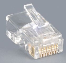 This is the specification that governs the physical connector on either end of an Ethernet wire. This is what regulates that there are 8 Positions and 8 Contacts. It also defines the design and dimensions of the clear plastic plug that terminates the cable.
RJ45
Registered Jack standard number 45 specifies the amount of wires in the cable, the order in which they appear, and the usage of the 8P8C physical connector.
Specifically, RJ45 defines two wiring standards: T568a and T568b:
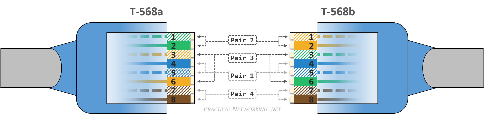
Notice the only real difference between the two standards are the colors of wire pair 2 and pair 3.
Twisted Pair
Twisted Pair wiring is a type of cable which uses eight individual wires in a bundle. The eight individual wires are paired in sets of two, and each pair is twisted around each other. This creates four pairs of wire, each of which serve as a channel through which data can be transmitted.
The pairing of the wires is very important, and we will look at why later on in this article, but the short version is it helps negate and minimize the effects of Crosstalk and Electromagnetic Interference (EMI).
There are two prominent types of Twisted Pair wiring, a Shielded variant and an Unshielded variant:
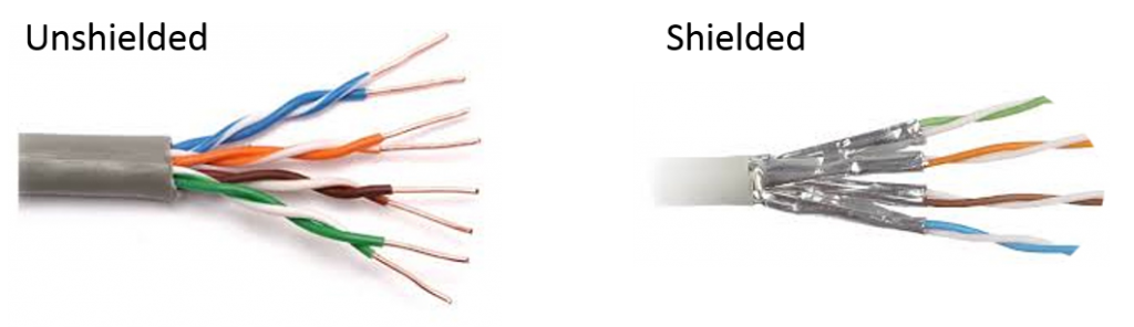
Notice in both cases, the pairs of wire create four distinct channels or lanes through which data will be sent.
Unshielded Twisted Pair (UTP)
This is the more commonly deployed variation. There is no additional shielding against electromagnetic noise, but none the less, UTP can carry a signal reliably due to innate features of twisted pair wiring. We will explore these in more depth later on in this article.
UTP is less expensive, more (physically) resilient, and more flexible. These attributes typically make UTP the preferred choice.
Shielded Twisted Pair (STP)
STP has additional shielding around each pair of wires and then one more shield around all four pairs. This helps contain and isolate the electromagnetic noise that occurs when signals travel through a wire.
That said, if any part of the shielding is damaged, or if the wires aren’t perfectly grounded on either side of the connection, the shielding can act as an antenna and introduce additional electromagnetic noise from stray radio waves and Wi-Fi signals in the air.
Moreover, the STP wire must also be coupled with shielded 8P8C connectors to ensure the additional shielding is present throughout the full end-to-end spectrum of the wire.
As you can imagine, STP is the more expensive variant. STP is also more fragile than its UTP counterpart – the shield is prone to tear if the wire is bent excessively. As a result, it hasn’t seen as much widespread use as UTP.
STP is typically reserved for use in areas with extreme levels of electromagnetic interference. For instance, in wiring that has to pass over or near any sort of power generator or heavy machinery.
Ethernet
As was said before, Ethernet is a family of specifications that governs a few different things. One of those things are all the different wiring specifications: 10BASE-T, 100BASE-TX, 1000BASE-T, and so on.
Ethernet also describes how to send bits (1s and 0s) across each wire, as well as how to interpret those bits into meaningful frames. For example, Ethernet states that the first 56 bits of every frame must be alternating 1’s and 0’s (known as the “Preamble”). The next 8 bits must be “10101011” (known as the Start of Frame delimiter). The next 48 bits are the Destination MAC address. The next 48 bits are the Source MAC address; and so on, until the entire frame has been transferred.
Below, we’ll describe some of the wiring standards specified by the Ethernet standard.
### BASE T* Terminology
This set of terms all refer to how the wires are used inside the cable. For instance, which ones are transmitting, which ones are receiving, how they transmit signals, and at what voltages?
There are three parts to this term, so let’s discuss them each individually first before we look at any specific standard:
100 BASE-T
The number at the beginning simply refers to the speed of the wire in Millions of bits per second, or more often referred to as Megabits per second (Mbps). A wire rated at 100 Mbps can theoretically transmit 100,000,000 bits per second, which equates to roughly 12.5 MegaBytes per second (MBps). Notice the capital B vs the lower case b to refer to Bytes vs bits.
An Ethernet cable rated at this speed is sometimes also referred to as Fast Ethernet. This is in contrast to a regular Ethernet cable which is rated at 10 Mbps, or Gigabit Ethernet which is rated at 1000 Mbps.
100 BASE-T
The term base is short for baseband signaling. Its counterpart is broadband signaling. When these terms originated, the difference between them was baseband signaling sends digital signals across the medium, whereas broadband sends analog signals across the medium.
The difference between a digital signal and an analog signal is the number of possible interpretations of each signal.
An analog signal can represent a theoretical infinite amount of values. For instance, a certain voltage on a wire might represent a green pixel, and another voltage might represent a red pixel, and so on and so forth until every pixel in an image is transmitted across the wire.
A digital signal can represent a finite amount of values – typically just two: 1 or 0. If the same image from above were being sent across a digital wire, a stream of 1’s and 0’s would be transmitted. The receiving end would be able to interpret the binary values as a series of numbers, perhaps based upon the RGB color codes, to represent each colored pixel.
The main difference being, at any given time on an analog wire, a plethora of signals (and therefore values) can be read. Whereas on a digital wire, at any given time the signal can either only represent a value of 1 or a 0, and nothing else.
This allowed digital transmission to be more error resistant as the wire’s entire voltage range at any given time is only divided into two possible values (1 or 0). Whereas an analog signal is more prone to transmission errors because any slight distortion will change what the other end interprets entirely.
For example, consider a case where some sort of interference or degradation of service caused the voltage received on a wire to be slightly different than what was initially sent.
In an analog world, since each voltage value could represent any one of millions of colors for an individual pixel (for example), a modification of the received voltage would create a distorted image.
Where as with Digital transmissions, the entire possible voltage range on the wire is divided to transmit only two values: 1 or 0 — which means it would take significantly more interference to modify the voltage transmitted enough to turn a 1 into a 0, or a 0 into a 1. The slight difference in received voltage would likely still be in the range of voltage values which communicate what was initially sent.
This image illustrates the effect very plainly. Notice as the signal quality degrades, the digital transmission can still interpret a 1 or a 0, and therefore still display the image without any visible distortion. Whereas with analog, as the signal degrades, a slight degradation in the signal causes the receiver to interpret the wrong colors for given pixels, causing the image distortion (the image is from a blog post by Antenna Direct in Australia.
100 BASE-T
The “–T” stands for Twisted Pair. This is in contrast to other wiring standards like -2 and -5 which indicate Coaxial wiring with maximum ranges of 200~ and 500 meters, or -SR and -LR which are Short Range and Long Range Fiber Optic wiring standards.
With each individual part defined, we can now look at the two prominent specifications for Fast Ethernet (we will look at two specifications for Gigabit Ethernet later on in this article):
100BASE-T4
100BASE-T4 uses all four pairs in the bundle (all eight wires). One pair is used solely for Transmitting signals (TX). One pair is used solely for Receiving signals (RX). The remaining two pairs can be used for either RX or TX, and it’s up to both sides of the wire to negotiate which of the remaining pairs are used for what.
T4 is one of the earlier specifications for Twisted Pair, and doesn’t see much modern use due to unnecessary complexity in the design for very little gain over the 100BASE-TX iteration described next.
100BASE-TX
100BASE-TX uses only two pairs, one dedicated to TX, and the other dedicated to RX. The other two pairs on the wire are unused. You could very well construct a 100BASE-TX wire which only had 4 of the 8 wires in the correct pin-positions (1,2,3,6), but often the other four wires are still included mostly as place holders for the remaining pin-positions, as well as for future compatibility.
100BASE-TX (with all eight wires) is the commonly used Fast Ethernet specification today. However, it is often (lazily) referred to as simply T. Again, T is meant to refer to the category of Twisted Pair options, and TX is the specific standard that calls for using the pairs at pin-positions 1&2 and 3&6.
The point of defining each term above, independent from the others, is to give each reader a practical and technical understanding of what each term means. In practice, despite knowing the true meaning of the terms, it is often far easier to simply use the common term, even if it might be slightly incorrect — a little inaccuracy can sometimes save a lengthy explanation.
Why Crossover
There are many guides on the internet that describe when you need to use a Crossover wire verses a Straight-through wire. But very few sources really explain why it matters, or exactly how it works. In this section, we will explore these concepts with more depth.
The 100BASE-TX and 10BASE-T specifications both call for 8 wires in a twisted pair cable to be grouped into four pairs.
Of the four pairs, only two will actually be used: pair 2 and pair 3. Each individual wire in the pair is a simplex medium, which means the signal can only ever cross any one wire in one direction.
In order to attain full-duplex communication, some wires are permanently set aside for communication in one direction, and the other wires are permanently set aside for communication in the opposite direction.

The configuration of the Network Interface Card (NIC) will determine which pair is used to transmit and which pair is used to receive.
A NIC that transmits (TX) signals over pair 2 (pin 1&2) and receives (RX) signals over pair 3 (pin 3&6) is called a Media Dependent Interface (MDI) NIC. While a NIC that does the opposite (TX on pair 3, and RX on pair 2) is called a Media Dependent Interface Crossover (MDI-X).
PC to PC
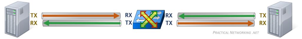
A PC uses an MDI NIC, which means PCs always transmit on pair 2, and receive on pair 3. But if two PCs connected directly to each other are both trying to transmit over pair 2, it would lead to a collision of their signals. And worse, neither PC would receive anything on pair 3.
As a result, the pin-pairs need to be crossed on the wire, so that what is sent from one PC on pair 2, arrives on the other PC on pair 3, and vice versa.
Here is a simplified illustration (the colors below are irrelevant, they simply indicate two different paths, for two different directions of the communication):
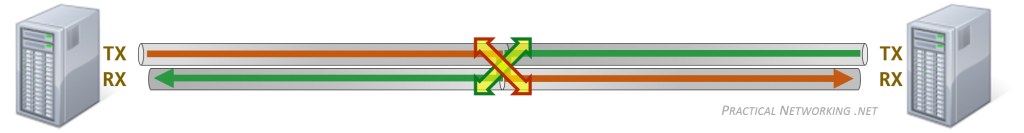
Notice both PCs can transmit signals through a dedicate channel, and due to the cross of the pairs in the wire (represented by the giant X), both PCs can receive what the other transmitted from a dedicated channel.
Hence, a connection from a PC directly to another PC requires a crossover cable.
PC to Switch to PC
A switch is a device that is meant to facilitate communication between two PCs on the same network. To that end, a switch NIC uses the MDI-X specification, which means a switch always transmits on pair 3, and receives on pair 2 (the exact inverse of an MDI NIC on a PC).
This causes the switch to have a built-in crossover function. The wire doesn’t need to cross the pairs, because the switch will take care of it:
As you can see, a PC connected to a switch can simply use a straight-through cable, and let the Switch deal with crossing the pairs. The end to end path remains consistent: every device is transmitting on its TX ports, and receiving on its RX ports.
PC to Switch to Switch to PC
We discussed earlier that two PCs connected directly to each other require a cross in the wire since they both use the same wire pairs for TX and RX. Similarly, two Switches connected to each other also use identical wire pairs for RX and TX.
As a result, we have to account for this by introducing yet another crossover between the switches:
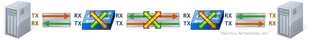
From the diagram above, we see that a switch connected to another switch requires a crossover cable.
In this way, the end to end path remains consistent. The PCs are both transmitting and receiving on the expected wire pairs. And each direction and step along the path always goes from a TX pair to an RX pair.
Routers and Hubs
But what of routers and hubs? What type of NIC do they use?
It turns out, a Router, like a PC, uses the MDI specification – TX on pair 2, and RX on pair 3. As such, you can replace any picture of a PC in any of the illustrations above with a Router, and can easily determine which connections would require a straight-through cable and which would require a crossover cable.
Furthermore, a Hub’s ports use the MDI-X specification – TX on pair 3, and RX on pair 2. You can replace any picture of a switch above with a Hub and can also easily determine what cables are required.
Ethernet Cable Wiring Diagram
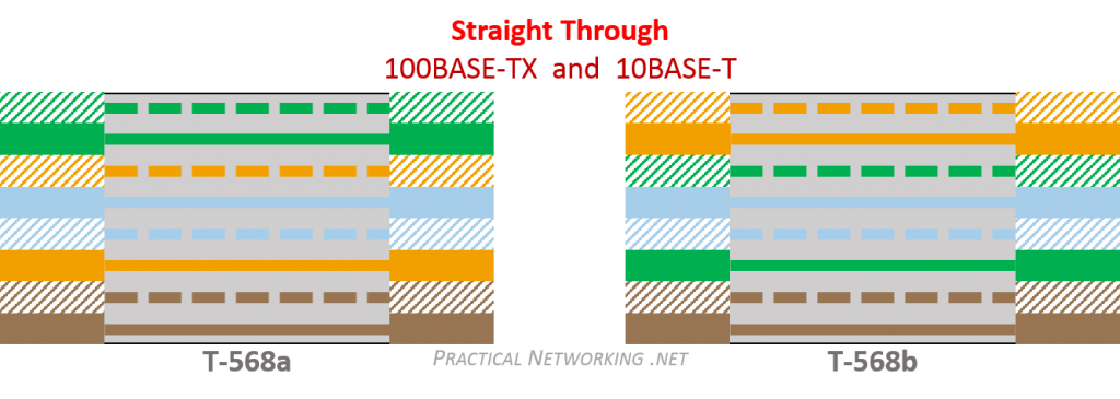
Recall that there are two standards for the colors in the RJ45 specification: T568a and T568b. The standard being utilized on either side of a Twisted Pair wire is what determines whether the cable is straight-through or crossover.
To make a Straight-through cable, simply order the wires on both sides of the cable to one specification (either both T568a or both T568b):
To make a Crossover cable, simply use one standard on one side, and the other standard on the opposite side:
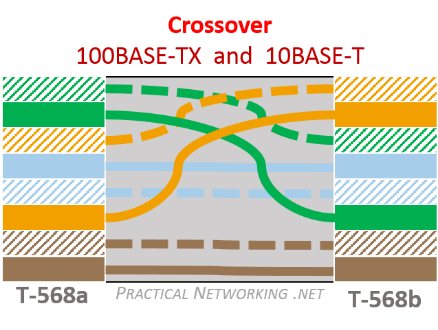
Note that wire pair 1 and pair 4 are not used (the blue and brown wires). You could, theoretically not include the wires in the cable at all, but this would make keeping the remaining wires in the proper order rather difficult.
Moreover, since they are not used, they do not need to be crossed in a crossover cable. However, the Gigabit specification does require using all 8 wires, and often all pairs are crossed for consistency. We will discuss Gigabit Ethernet later in this article.
And lastly, remember that the signal doesn’t really care what color the wire is. As long as the correct pins are connected to each other, communication will work. You could use all green wires, and as long as Pins 1&2 are connected to Pins 3&6 on the other side (and vice versa), you would have a fully functioning cross-over wire. But just because it works, doesn’t mean it is a good idea – such a cable would be a nightmare to maintain.
Easy Memorization Chart
We can aggregate everything we learned above regarding crossover wires and straight-through wires into a simple chart:
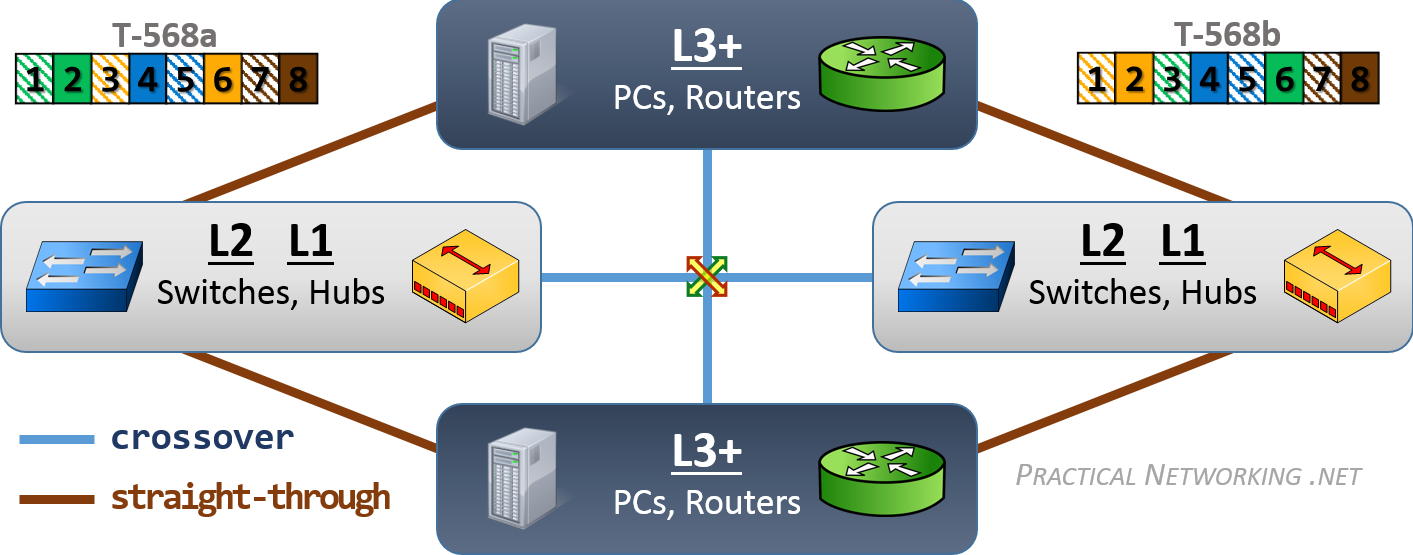
A benefit to how the graphic above is displayed is that it makes it very easy to sketch out. Simply draw L2/L1 on the left and right, and L3+ on top and bottom and connect everything to each other. The lines that cross each other require a crossover cable when connecting devices that operate at those layers of the OSI model. The lines that connect straight to each other require a straight-through cable.
In summary:
An L1 or L2 device connected to another L1 or L2 device requires a crossover cable.
An L1 or L2 device connected to a L3+ device requires a straight-through cable.
An L3+ device connected to another L3+ device requires a crossover cable.
Or even simpler:
Like devices require a crossover cable.
Unlike devices require a straight-through cable.
Auto MDI-X
Despite the simplicity of knowing when to use a straight-through cable verses a crossover cable (after it has been properly explained, of course), the fact that a choice exists at all has caused all sorts of downtime and headaches for network engineers across the industry.
As a result, a feature was created which allows the two devices to dynamically determine and switch their TX and RX wire pairs if necessary. This feature is known as Automatic MDI-X, or Auto MDI-X.
Auto MDI-X allows the use of a straight-through cable for every connection, and lets the two endpoints dynamically determine whether they need to inverse their TX and RX pairs.
Auto MDI-X is an optional feature for 100BASE-T implementation, and a required feature for all Gigabit Ethernet devices.
How does Auto MDI-X Work?
But how does Auto MDI-X work? How do the two parties determine which pairs of wires should be used for TX and which pairs should be used for RX? Which of the two parties should switch the TX and RX pairs if it is determined to be necessary? We will look at the inner workings of Auto MDI-X in this section.
Remember, the goal of the Crossover cable is to ensure one party’s TX pins are connected to the other party’s RX pins. For successful communication down a cable, a TX wire cannot be connected to another TX wire. Essentially, one NIC must use the MDI specification, and the opposing NIC must use the MDI-X specification. Here is how Auto MDI-X accomplishes this:
Both parties start by generating a random number in the range of 1-2047. If the random number is odd, that party configures their NIC to the MDI-X standard. If the random number is even, that party configures their NIC to the MDI standard. Both parties then start sending link pulses through their elected TX wire pairs.
If both parties are successfully receiving the other’s link pulses on their RX wires, then both sides do nothing further, as they are successfully transmitting on their TX wire pairs, and receiving on their RX wire pairs.
If both parties are not receiving the other’s link pulses, then they must have both picked an odd number or both picked an even number. Therefore, one of the parties must switch their TX and RX wire pairs to the other specification (MDI vs MDI-X).
But the parties can’t both switch to the opposite specification, because then their TX and RX wires would still not be offset. Instead, a system was devised that randomly switches the pairs at random intervals until they correctly match up.
That randomly generated number from earlier (1-2047) gets cycled forward in order for the parties to select a new specification (MDI vs MDI-x). But that number cannot simply be increased by one, because then both parties would go from odd to even, or from even to odd. In other words, if both parties had elected MDI originally, they would then both switch to MDI-X, which would still cause a TX wire pair to be connected to a TX wire pair.
Instead, that number is cycled forward through what is known as a Linear-Feedback Shift Register.
A Linear-Feedback Shift Register (LFSR) is an algorithm that cycles through every number combination in a certain range without ever repeating a number until every number has been reached. The numbers are cycled through in a predictable, but random order (aka not sequentially but in a consistent order).
For example, if the two parties picked a starting value of 1000 and 2000, whether their next number in the LFSR sequence would be odd or even would be completely random. However, if both parties randomly picked the same starting value, they would each have identical sequences through the LFSR.
This cycle happens every 62 milliseconds, with a random variance of +/- 2ms. If one of the parties switches their wire pair at 60ms, and the other party was planning to switch at 64ms, there would be 4ms where the TX and RX pairs are perfectly aligned, which stops further cycling and completes the AutoMDI-X process.
This process continues as many times as is necessary until the two peers have lined up their TX and RX wire pairs.
But this begs the question, what are the odds of both pairs picking the exact same number and the exact same intervals each time they cycle their number. We can determine this with a little math.
The odds of picking the same starting value are 1 in 2047. The odds of picking the same interval variance is 1 in 4. Which means the odds of both parties both switching their MDI/MDI-X specification at the exact same time twice in a row is 1 in 8188.
The cycle happens every ~62 ms, which means in a full second there are 16 possible intervals. The odds for the two parties to have the exact same cycle timing for the entire second are 1 in 4,294,967,296 (4.2 billion). The odds of that happening combined with both parties starting with the exact same random number are 1 in 8,791,798,054,912 (8.7 trillion). Pretty good odds, considering at worst this will only cost you an extra second of waiting for the link to come up.
Why Twisted Pair?
It is often simply accepted as fact that most networks use Twisted Pair wiring for their physical connections. But why? What about Twisted Pair has made it the predominant cabling method in computer networks?
There are two main reasons, and both have to do with Electromagnetic Interference (EMI): The first reason is that using a pair of wires greatly reduces the outbound EMI emission. The second reason is that twisting them around each other greatly reduces inbound, or induced, EMI.
Both of these are very desirable traits when the wire is often closely bundled with other wires over long distances (think data centers or wiring closets).
Reducing EMI Emission
It is a fact of life that any signal or electrical current running through a wire emits some degree of EMI that can affect neighboring wires – also known as Crosstalk. This EMI emission can be compensated for with additional shielding, but Alexander Graham Bell devised a clever method to negate the effects of Crosstalk.
His strategy was to use two separate wires — one of them sending the original signal, and the other one sending the exact inverse of the signal. This causes both wires to emit the exact inverse EMI from each other, thereby negating their effect.
To put it in simpler terms, if one wire transmits +10v of electrical voltage and leaks +0.01v of EMI, then the other wire will transmit -10v of electrical voltage and consequentially leak -0.01v of EMI. Their combined emissions cancel each other out.
This is referred to in the electrical engineering world as a Balanced Pair, and is represented in twisted-pair wiring with the TX+ and TX- wire.
This allows you to use wiring schemes that don’t require heavy investments in shielding, and is half the reason for the prolific use of Unshielded Twisted Pair (UTP) cabling in the networking world. However, so far we’ve only answered why we use a pair of wires, we will look into why they are twisted next.
Negating Absorbed EMI
Despite strategies like the Balanced Pair described above, there is no getting away from all sources of Electromagnetic Interference (EMI). Stray radio frequencies, wireless internet, Bluetooth, spy satellites, and cell phones all contribute to stray EMI.
But Alexander Graham Bell came through for us again, and devised a brilliantly simple, yet effective, method to nullify ambient EMI.
The basic concept takes advantage of EMI being stronger the closer in proximity you are to the source. If the two wires take turns being closest to the EMI source, they will each absorb an equal amount of interference. Take a look at this simplified diagram:
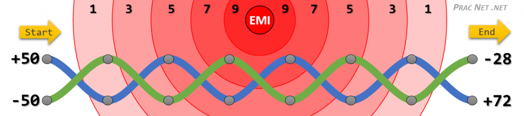
The blue wire starts with +50v, and the green wire starts with the exact inverse, -50v. The source of the EMI is the red circle, and each wave that surrounds the EMI source impacts the wires progressively less and less. If you only add the EMI at each grey dot (the top and bottom of each twist), both wires end up receiving +22v of interference.
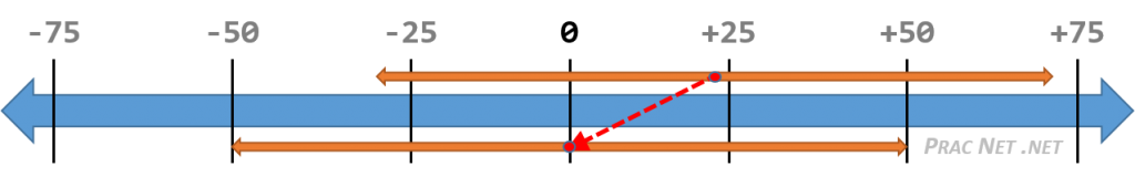
Even though the final voltage received on the right side of the wire is different, notice that the difference in voltage is consistent throughout the twisted pair of wires: it is always 100v apart. The EMI affected both wires identically. You could easily calculate the difference of the final values (100v), and display it on a number line to determine the starting voltages were +50v and -50v:
Sending Bits
If you recall, data is sent across a cable in a digital signal, which is to say, as a stream of 1’s and 0’s. But how exactly is a Twisted Pair wire used to send actual data across the wire? We will use a bit of an over simplification to describe the basic premise.
Sending a signal down the wire is nothing more than applying voltage to the wire for a certain amount of time. The two parties will agree on a clock rate, also known as frequency, which determines how long each ‘instance’ of voltage must be applied. For the purpose of this simplified example, we will refer to this as the position. At any given time, each position can only mean either a 1 or a 0 being sent down the wire.
Different standards call for different voltage levels, and for the purpose of this simplistic description the true voltage doesn’t actually matter. But we will proceed to describe it using 100BASE-TX which prescribes a voltage range of +2.5v to -2.5v.
To send a 1 in a given position, the transmitter will send +2.5v down the TX+ wire. To send a 0, the transmitter will send -2.5v down the TX+ wire.
The TX- wire will always do the exact inverse: -2.5v to send a 1, and +2.5v to send a 0.
This is what it would look like to send a binary string of 110010101110:
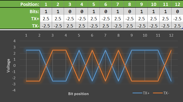
Note that the graph above does not depict the physical layout of the wire (aka, this isn’t the twisting of the wire pairs). It just represents the alternating +2.5 and -2.5 volts being sent down the TX+ and the TX- wires. The twists in the twisted pair are (or should be) uniform across the length of the wire. As we pointed out before, you can see that the wires are always sending the exact inverse voltage of each other, and everything is neat and horizontally symmetrical.
Along the wire, noise is introduced from various EMI sources. We’ll apply a different amount of noise at each position of our bit stream and take a look at what is received on the other end:
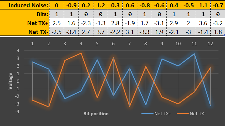
Notice the graph is no longer as neat and symmetrical. The wires are still sending the inverse of each other, but offset by a constant value. Our nice and neat values of +2.5v and -2.5v are gone.
BUT, the receiver isn’t looking for exactly +2.5v or -2.5v. Instead, it is simply looking for which wire sent the higher voltage. If the TX+ wire sent the hire voltage, then the signal for that position must have been a 1, and if the TX- wire sent the higher voltage, then the signal for that position must have been a 0.
Or, to put it simply, on the graph above, if the blue line is on top, the transmitted bit at that position is a 1. And if orange line is on top, then the transmitted bit is a 0.
Notice also that even though the values were affected by EMI, they were both affected identically – they both went up or both went down by the same amount. At any time on the receiving graph, the value of the TX+ wire and the TX- wire are always 5v apart, just like they were in the sending graph. As we discussed earlier, this is due to the physical twisting of the TX+ and TX- wires.
In this way, the receiving end can piece together the signal, one bit at a time, despite whatever EMI might have affected what was originally sent. As you can see, UTP is not immune to noise, but it has functionality to negate the effect of noise.
Gigabit Ethernet
We’ve discussed Fast Ethernet (100 Mbps) in great detail. Now we move on to discussing Gigabit Ethernet (1000 Mbps, or 1 Gbps).
The first major difference is the gigabit standards require the use of all four pairs (all eight wires), unlike Fast Ethernet which only utilizes two pairs of wires. As a result, in Gigabit Ethernet, all four pairs must be crossed when building a Crossover cable.
If you recall, there are two wiring specifications proposed by the RJ45 standard: T-568a and T-568b. Below are images which depict what each of them look like when all four pairs are crossed:
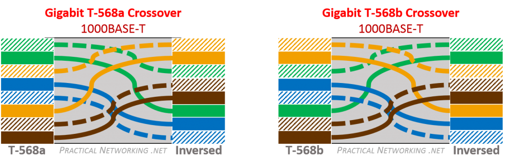
That said, Gigabit Ethernet requires Auto MDI-X. As a result, you are safe to simply use straight-through cables everywhere and let the NICs determine whether they need to simulate a crossing of the wire pairs.
There are two wiring specifications within the Gigabit Ethernet standard:
1000BASE-TX
This standard of Gigabit Ethernet uses all four pairs, but it dedicates two of the pairs for TX, and the other two pairs for RX.
Conceptually, this is a simpler process than how 1000BASE-T operates, but regrettably it requires upgrading all the twisted pair cables that have already been run from the common Category 5 or 5e to the more expensive Category 6. As a result, 1000BASE-TX has not seen much adoption in the industry.
1000BASE-T
This is the predominant Gigabit Ethernet standard. It uses all four pairs at the same time, in full duplex mode – each of the four pairs can be used for both RX and TX, at the same time. This is done with a process called Echo Cancellation, and we’ll explore that in more depth in the next section.
The primary benefit to this wire standard is you can achieve gigabit transfer on the much more prevalent Category 5e cables without being forced to upgrade all your twisted pair cables tot he more expensive Category 6.
1000BASE-T cable is often incorrectly referred to as 1000BASE-TX. This is most likely because in the Fast Ethernet world, the predominant cable was 100BASE-TX. Frequently, the cabling standards are also sometimes lumped together as 10/100/1000 BASE-TX. In reality, the most popular wiring specifications for each speed class are 10BASE-T, 100BASE-TX, and 1000BASE-T.Full Duplex on a Single Wire Pair
We learned in the last section that 1000BASE-T can send and receive signals on the same wire pair at the same time. We will discuss how this is possible in this section. First, we’ll start with an analogy to explain the premise.
Have you ever talked to someone on the phone and could tell that they put you on speakerphone because you could hear your own voice echoed back? This is an outcome of your voice being played on their speakerphone, bouncing around the room they are in, and being picked back up by their own phone’s microphone. This is known as an echo.
High end speakerphones can negate this effect by extracting the sound waves of what the speaker emitted from the sound waves of what the microphone is picking up — this process is known as Echo Cancellation.
Echo cancellation is also the basic concept which allows a Gigabit Ethernet wire to both send and receive data on the same wire pair at the same time. The basic premise is if you know what you sent, you can extract it from what you received.
Recall that sending a signal is nothing more than applying voltage to a wire. Conversely, receiving a signal is nothing more than reading the voltage observed on a wire.
If a sender applies voltage to a single wire in the following pattern:
+0.5v , +1v , -2v , -1v
And at the same time that same sender reads the voltage and observes the following pattern:
+1.5v , 0v , -2.5v , +1v
The sender can subtract the voltage it initially sent from the voltage it just received to determine what voltage the other end must have applied:
+1v , -1v , -0.5v , +2v
In this way, the same wire can be used to both send and receive signals (data) at the exact same time.
Again, these values are merely examples in order to explain the basic concept. In reality, the voltage levels are very different, and also account for induced EMI and electrical echoes along the copper wire itself. In addition, we are only showing Echo Cancellation from the perspective of a single wire in a twisted pair – the opposite wire would still be sending the exact inverse voltage, as discussed earlier.
Using this strategy, all four wire pairs can be used for both TX and RX at the same time. The wire pairs are still Twisted Pairs, and therefore still use the same strategies to negate the inbound and outbound EMI discussed earlier.
Summary
If you’ve made it this far, then you now know just how much there is to Ethernet and Twisted Pair wires. It was a little humbling to learn about it over the years and publish this article. So much technology goes into each wire, yet I have thrown away countless cables without a second thought.
Ethernet wiring is definitely full of technology that we easily take for granted. And to think, even this article left out significant detail in order to remain (relatively) simple.


Heck of a job there, it ablstuoely helps me out.
Glad you liked it, Bobbo. Thanks for the read!
Ed , i am already an academic fan of yours. wonderful clarity in whatever you explain. Going thru your TLS course
Great piece of content here. Very good and I like the graphics!
Hi Jason, glad you enjoyed it. Thanks for the comment!
Great article, very easy to read and full of details. I think it would be worth mentioning that:
a) “Millions of bits per second (Mbps).” can be abbreviated to “Megabits per second”, which is the same, but I never heard anyone saying “millions of bits” in a conversation,
b) modern switches/routers don’t require crossover cables anymore to connect with each other.
Hi Mike, glad you enjoyed the article. Good point about Millions of Bits vs Megabits, I’ve updated that section. As for switches/routers not requiring crossover cables anymore, that is a function of AutoMDX, which has its own section going into the details. Thanks for the feedback!
Great article, very well written and easy for a semi-technical mind to grasp. This makes all of this stuff much more understandable. Thank you!!!
nice work thank you for scharing this post
Great article and appreciate the effort you have put in to describe every bit patiently. Kudos!
Bookmark’d..
Fantastic explanation !
another badass high quality breakdown, I love this site!!
Hello,
Thank you for sharing it! I have a question for 1000 base T and Auto MDIX
Since 1000 BASE T is full duplex, each pair can transmit and receive, then why it is necessary to use auto MDIX?
Full Duplex on each wire pair still require a coordinated channel between the two receivers. Auto MDIX would establish those dedicated channels, upon which signals can be sent in both directions.
Thank you for your kind reply. In that case, the purpose of of the Auto MDIX in 100BASE-T and 1000BASE-T are different. In 100BASE-T, it is used to pair the Tx to the Rx. For 1000BASE-T, it is used to find the logical channel A on one device to logical channel A on the other device.Is that correct? thanks
Yes and no =).
For 100BASE-T, the purpose of Auto MDIX is to establish two channels, using pin pair #2 and #3. The options for which are:
One channel (represented by
---) is used for data transfer one direction, and the other channel is used for data transfer in the other direction. The remaining pin-pairs are unused so what they are connected to (if at all) is irrelevant.For 1000BASE-T, the purpose of Auto MDIX is to establish four channels, using a pair of pin-pairs (#2/#3 and #1/#4)
All four channels are used for data transfer in both directions.
If for some reason pin pair #2 was connected to pin pair #4, the link would not come up. In fact, Auto MDI-X would fail because the process described above only runs on pin pair #2 and #3 — the result will determine if the “channels” are straight through or crossed.
So, while each of the four pairs is used in the same way on the wire level, it is still essential for the slightly higher level protocols that combine these 4 data channels into one (times two, for each direction) to know which is which and which is connected to which?
Yes, all the understanding of how to use which wires is all handled by the NIC. The NIC (whose job is to put data on the wire) will do Auto MDX to figure out what standard is being used and act accordingly.
All the other “higher level protocols” (L3+) are happily abstracted away from the process. That is part of the benefit of the OSI Model — each layer abstracts away their role from the other layers.
I was under the impression that all pairs in a RJ45 cable are created equal. Any pair can pair with any other pair. Why can’t pin pair #2 pair with pin pair #1?
This discussion thread forced me to rethink the purpose of auto MDIX. Assuming RJ45 allows #2#1 combination, why do we need auto MDIX to negotiate 4 days channels at all?
Ee, hand’s down this is one of the best introduction of the physical aspects of Ethernet. This really helped me to piece together hardware and software aspects of the networking stack.
Really good article. Thank you very much.
Thanks for spreading knowledge
Thank you for your excellent articles. Unfortunately it is rare to find information explained as lucidly as you have done.
I have a question though regarding your explanation of “broadband” and “baseband” when discussing the meaning of “BASE” in “BASE-T”. In my mind, that section leaves one with the impression that “analog = broadband” and “digital = baseband” in such a way that only baseband signals partake of the advantages which digital signals offer over analog. But it is quite possible (and is commonplace) to have a broadband signal carry digital information by digitally modulating an analog carrier. Similarly a baseband signal can be analog. Would you care to clarify? Thanks.
Please keep up the great work!
Even if there was such a thing as a crossover cable for 1000base-t (there isn’t), the wiring you show wouldn’t be right. Think about how you wired that cable, if you flipped it end to end, the wiring would be different. To help maintain balance and eliminate cross-talk, they are purposely alternated between tip/ring (or -/+), you would never have two tips (white) or two rings (colored) next to each other (or you would never have two +’s or two -‘s next to each other).
Hi Jerry,
There is a thing as a crossover cable for 1000base-t, they just aren’t needed because of Auto MDI-x.
Flipping a cable “end-to-end” isn’t the same as a crossover cable, that would be a Rollover Cable. In a Rollover cable, each of the 8 pins are switched. (aka, 1 with 8, 2 with 6, etc).
By contrast, a crossover cable, has each pair flipped. Pair 1 (pins 4&5) is switched with Pair 4 (pins 7&8), and Pair 2 (pins 1&2) is switched with Pair 3 (pins 3&6).
Finally, the position of the wires in the 8P8C connector do not designate what wires are twisted around each other. Regardless of the final position in the 8P8C connector, the white/color is always wrapped with the correlating color wire. The crosstalk is eliminated (or negated) throughout the path of the twisted pair — not in the final few centimeters of the connector.
Great article !!
1.Why do they use serial cables that are low speed compared to ethernet cables ?
Honestly, I don’t see serial cables used very much these days. They are referred to often in Cisco certification curriculum, though. I imagine because they provide a good illustration of point to point links. But in reality, Serial cables are not used nearly as often these days.
Great article man, but serial cables or roll over cables are still required to connect to console of devices like switch, router, Wireless controller etc. for configuration through CLI.
Great post thank you for all the time and effort put into the phrasing and diagram making
2018
Glad you enjoyed them, DJ. =)
This excellent wwebsite truly has aall of the
information I wanted concerning this subjecct and didn’t
know who to ask.
great job! it has all the information some one need to know and the way you describe every thing is just perfect . thanks for sharing your knowledge:)
Howdy would you mind letting me know whjich hosting
company you’re using? I’ve loaded your blog in 3
completely different internet browsers and I must ssay this blog
loads a lot quicker then most. Can you suggest a goood internet hosting
provider at a reasonable price? Cheers, I appreciate it!
Awesome Content
Great page, thanks.
Spotted one typo: “Typical EMI emission only affects signaling in the range of micro-volts (mV)”
See if you can get a mu in there 🙂
Glad you liked it. Great catch, fixed it!
I just encountered your page by chance while grinding for CCNA exam,You really provided significant foundational knowledge by describing essential informations for real networking,Thanks you so much for your clarifications,from Turkey.
fantastic articles ! feel like I am in a class and there is a perfect teacher, keeping pace and exposing just enough details so that we learn something and yet, is easy to digest.
I have a NetGear Prosafe GS108T switch. I am connecting 4wire cable to it (M12 to RJ45 cable), basically 100M. It does not establish a link.
I am wondering because only pins 1,2,3 and 6 are phsyically connected, Pins 5,7 and 8 are not there and I am assuming that is the reason switch is not able to auto-negotiate down to 100M. Is that correct? Now If i connect the same cable to a 100M switch, the link is established.
That seems reasonable. If a gigabit link tries to auto-negotiate the speed and doesn’t detect pins 4,5,7,8, it might simply fail and call the link down. Maybe try hard setting the speeds to 100, see if that gets you any further.
Why pair 1 is blue wires instead of green?
How do I know Which devices like to transmit on 3,6 instead of 1,2?
Is there any way to know that both devices transmit on same pin pair?
The effect would be the inability to communicate on the given wire. That could be an indication that both devices are communicating on the same pin pairs.
That answer is in this section. But the summary is PC’s and Router’s use MDI specification (TX on Pair 2), and switches and hubs use MDI-X specification (TX on Pair 3). But remember, this is for the 100 Base T and 100 Base TX specification. Gigabit Ethernet uses all four pairs for both TX and RX.
Mr. Harmoush,
I’ve worked in the IT field for over 20 years. I’ve sat in many classrooms and read many books in order to learn new technologies and prepare for certification exams. (Novell Netware 3.x, 4, and 5; Windows NT 4, A+, Network+, Security+, Cisco CCNA, CCNP, JNCIA, and many others.)
I have never, over the course of those 20+ years, had the understanding of Ethernet that I now have thanks to your exceptional teaching abilities and your willingness to share your knowledge with others.
I listed some of the training courses I’ve taken over the years not to promote my abilities but to give you an idea of how many training courses I’ve completed over the years – and to make clear that I’m qualified to differentiate a trainer versus a “good” trainer versus an EXCEPTIONAL trainer/teacher. You are clearly the latter – EXCEPTIONAL!
Warm Regards,
John
Whoa John. Thank you so much for the very kind words. I’m blushing ;).
Glad you enjoyed the resources on the blog. Thanks again for posting!
PS: Spreading the word about the content here is always appreciated, but of course never required. 😉
I am new to the world of networking and communications, knowing very little previously of how information is transferred. This article has answered every question I had with detail and simplicity. One more though… Are PCs and Routers today mostly Auto MDI-X or are they fixed?
Hi Ty! Thank you for the kind words =) I’m glad you enjoyed the article.
Pretty much anything with a NIC made in the last 10 years supports Auto MDI-X. Remember, Auto MDI-X is required for Gigabit interfaces, so if you have a device that is capable of Gigabit communication, even if it is set to 100 mbps, it can still perform Auto MDI-X.
Hope this helps =)
Excellent article, thanks for posting this. As you said, many other articles out their fail to explain the ‘why’ of crossover cables, and this does a great job of answering that. Great stuff!
This is an excellent resource for understanding how the various flavors of ethernet work. As many others have noted, I have been around the IT industry for several decades and have never found such a clear, concise and understandable explanation of ethernet wiring, well done.
When I remodeled the house 15 years ago, I put in cat 5e cable everywhere and blindly connected all 4 twisted pairs to the RJ45 jacks. Everything worked just fine with 10 Base-t, then I upgraded to 100 Base-T and didn’t think anything of it (files were not very big then). Now I have upgraded the hardware to support gig ethernet and I am trying to copy large amounts of data from my old server to a new server and I am finding that I am only getting about 10 MB/second (so the upgrade to 100 Base-T accomplished nothing). Based on your explanation here, I am suspecting that there is a wiring issue with the Cat 5e terminations to RJ45. To test my understanding, can you verify that it is safe to assume, that all wiring should be straight through in my situation (e.g. straight through patch cables from device (router, PC, hub, to wall) and straight through wiring in wall (eg RJ45 female to RJ45 female)?
Thanks much
I think it depends on what else is connected to the patch panel. The patch panel is considered simply an extension to the wire. So if you are connecting two PC’s directly via the patch panel, then somewhere there needs to be 1 (or an Odd) amount of crosses on the wire. Meaning you could do PC –> ST –> PP –> CO –> PC, where ST = straight through, PP = patch panel, CO = cross over.
Either way, if the devices are modern in any way, they probably support Auto MDX and you are safe to use straight through everywhere.
Great article!! I have a question about a single ended signal down a twisted pair. What is typically done with the wire not carrying a signal in the pair? Is it tied to the shield and then to ground on both ends? Is it just tied to the shield? Is it tied to the shield and ground only on one end? If so which end? If you can please add theory to your answer so I understand why it’s common practice.
THANKS!!
Does it matter to exchange the solid-color and striped-color of a pair? By accident I made a patch cable where on one side the connector was correct (568B configuration), but on the other side the in the connector I switched the solid-blue and blue-striped wire. So it is still within the pair. The cable seems to work perfectly as I get my full Gbit/s throughput, but I wonder whether I should fix it?
THANKS!!
Many thanks for the explanations about this interesting argument. Recently, I made a crossover cable in gigabit ethernet, but the data transmission has got worse, then observing another cable I had managed years before, I noted that I had gone from a crossover involving just 4 wires, such as for Fast ethernet. So, I repeated the same old configuration set for Fast ethernet and the issues on crossover were fixed. I have Cat 5e cables. So why the crossover cable made for Gigabit ethernet doesn’t work in may case? Thanks in advance for any answer.
I searched for crossover schemes and I’ve found that 1000base-t and 1000base-tx are different.
So I’m an electrician and my boss has us pulling cat5e on some apartments. My understanding is that each jack point has to run straight to the server/router, but he has us running one home run then looping to the 1 or 2 other jacks. He insists that it’ll work, so my question is can you wire ethernet cable in series like he’s saying or am I right and this will never work?
It’ll work as long as only one of the 2 or 3 downstream jacks in series is used. If they try to connect 2 devices to the router/server with one cable, that will fail. Each device needs it own cable.
Hi Ed,
Great work. Thanks.
Could you also clarify how half duplex works with 10base-tx.
Or put it this way how CSMA/cd is achieved on a twisted pair where we know single wire in a twisted pair is basically a simplex either Tx or Rx, so what is the point of carrier sense when the medium is no longer shared like coax, basically collision free and in no need of a sensing mechanism. Or was there some sort of auto MDI negotiation for that allowing a single wire in a twisted pair to act as coaxial cable medium for CSMA/cd based communication.
Two things I am looking to understand firstly why half duplex was still supported after the invention of twisted pair when it makes no sense after shared medium standard like coax was deprecated. Secondly the mechanism how was half duplex possible in twisted pair when medium for both tx and Rx were different.
Regards,
Sorry 100base-tx or 100base-t4
Excellent explanation! thank you very much!!! now a question: consider a situation where 100Mb/s are enough speed, but extreme low noise is required… would it be better to implement 568A or 568B, as pairs are twisted each in a different way to avoid noise? would it be of any benefit not to connect pairs 1 &4 at all, or even connect them to ground? or any other advice for the case?.. thank you very much again…
The choice to use 568a or 568b wouldn’t affect the noise or EMI reduction. You’d want to go for Shielded Twisted Pair if you are in a heavy noise environment. (Or Fiber, preferably).
It’s not recommended to do something atypical with the wire otherwise (not connect 1&4, or connect to ground, etc). It’s just going to cause more headache later =).
Glad you enjoyed the write up!
This is amazing post and explanation. Thank you sooo much for this !
You’re welcome, Greg!
Fabulous article, there isn’t a rating high enough for it. Thank you a million times for your great explanations.
Thank you for the kind words, Mary =). Glad you enjoyed it!
Not even sure how I got here as I really didn’t need this info, but I happened to read the whole thing through. Now I know when to twist my pairs (and why).
Guess I have to get into networking or something now. Cheers!
Ha. That’s great =). Glad you found it interesting enough to read all the way through. =)
Absolutely blitzkrieged it ! Bookmarked
=)
I also printed it to PDF lol
Hi Nice explanation.
I have one doubt. Why does switches has different transmission and reception pin? If those were same then we could have only used crossover cable right?
Couldn’t tell you why it was designed that way =). But yes, if everyone used the same TX/RX pins, then crossovers could have been used everywhere.
What is the difference between Gb/s (Gigabit per second) and frequency (MHz) in network cables? For example: cat5 cable is 100Mb/s and 100MHz frequency and cat5e cable is 1Gb/s and 100MHz frequency. Is the “1Gb/s” the amount of data that can be transmitted and the “100MHz” the speed at which that data is transmitted?
The “MHz” is how often a symbol can be read from the wire.
In Ethernet/FastEthernet, a symbol is a single bit, 1 or 0.
Ethernet (10mbps) uses a frequency of 10mhz — 10 million symbols per second = 10 million bits per second
FastEthernet (100mbps) uses a frequency of 100mhz — 100 million symbols per second = 100 mbps
Both Ethernet and FastEthernet only use a dedicate single wire pair for traffic in each direction, so this 100mbps is in each direction (Full Duplex).
In Gigabit a symbol is two bits (00, 01, 10, 00)
Gigabit uses a frequency of 125mhz — 125 million symbols per second = 250 million bits per second.
Gigabit uses all four wires, hence 4x 250 = 1000 mbps.
Hope this helps.
Hi Ed, thanks for sharing your knowledge. I’m impressed with the way the subjects are detailed.. My development in Computer Networks is thanks to these extraordinary articles. I have a doubt about Ethernet and Fast Ethernet having a wire (TX+) and a wire (TX-) on (pair 2) and on (pair 3) having a wire (RX+) and a wire RX-). At the Fast Ethernet (100BASE-TX) the (pair 2) has pin 1 (TX+) and pin 2 is (TX-) and (pair 3) has pin 3 (RX+) and pin 6 (RX-). On the (1000BASE-T) and (1000BASE-TX) how is this question of the (TX+ and TX-)? An example of the (1000BASE-T) that in each (pair) uses one wire to transmit and the other wire to receive in full duplex on the same pair.
The “Pairs” of wire form a single channel which can be used to transmit data. The +/- designation is in reference to the Balanced Pairs within Twisted Pair wiring. Each Pair can only be used for one data stream.
In 10/100 Base T, only two of the “channels” are used (Pair 2 & Pair 33. The remaining two are unused.
In 1000 Base T, all four “channels” are used at the same time, to transfer traffic in *both* directions at the full time. That process uses Echo Cancellation to determine what the other side sent.
Does this clarify your question?
good job
Great article. Thanks.
But I have a question. Can we just use straight cabling rather than T568 standarts meaning WORANGE-ORANGE-WGREEN-GREEN-WBLUE-BLUE-WBROWN-BROWN without uısing t568 standarts.
I have couple cables like that and they work fine but since TX RX pairs are not twisted signal should be worse although i get gigabit over it without issue. at how much lenght or awg of wires will it matter
I just have this question taking space in my head for a long time
No words to say. Absolutely fantastic explanation. Thank you so much sir.
Your’re welcome, Zakir. Cheers!
Excellent explanations with very clear and informative examples and graphics. Congratulations.
Thank you, SK.
Great job Ed.
Thanks for this beautiful presentation!
I’ve been trying to understand how Gigabit Ethernet works, but everybody explained only how Fast Ethernet with its 100Mbps works, by using only two peers of wires, but never how Gigabit really works.
Now there is still a question 🙂
What about adding PoE into the mix and explain how it works?
I found elsewhere that Fast Ethernet uses wires 1,2,3,6 for data and 802.af type B uses 4,5,7,8 for delivering the 48 volts of current to power PoE devices, but there is also type A which delivers the PoE current on the same wires as the data does, but “magically” without any interference or adding errors to the data. So how it works 😀
Also how Gigabit Ethernet works with PoE, since it uses all 4 pairs for data when PoE can also use from 2 pairs in IEEE 802.3af or IEEE 802.3at to 4 pairs is IEEE 802.3bt.
The real questing is how does it it do it without having any electrical problems by overlapping the current for data with the current used for PoE.
Thanks!
Honestly, that is a great question and not something I’ve researched before. But if you know the answer, by all means come back and let us know =).
Great Job!!! Nicely presented !!!
Have a doubt, As per my understading and explained above
For 100Base-TX, Full duplex, Two pairs are used
MDI Mode: — Pair 2 –> Transmit direction
Pair 3 –> Receive direction
MDI-X Mode: — Pair 3 –> Transmit direction
Pair 2 –> Receive direction
Can you please confirm how the above is done in 100 Base-TX Half duplex mode, Si only one pair used for both Transmit and receive and only one direction at time??
The usage of the wire doesn’t change for half duplex. Half duplex “collisions” in Ethernet are actually just virtual — there isn’t an actual collision on the wire. The collision counters simply increment whenever a packet is both sent and received on the same ethernet cable.
Is it possible to connect two hosts to one 8p8c port as two 8p4c ports?
I mean host 1 is connected to 1-2-3-6 and host 2 to 4-5-7-8?
So… “can it be done” sure, but then you’d have to rewrite how one of the hosts communicates.
For instance, you’d have to figure out how to tell the “other side” of host 2 to use pins 4/5/6/8 instead of 1/2/3/6, which would involve re-writing nic drivers, and likely more trouble than it’s worth.
Whatever problem you are trying to solve, likely there are easy problems than trying to use a custom set of pins =)
Yes, it’s just a theoretical question, an experiment.
I mean i will be using the 1st 4p4c cable 1-2-3-6 on both sides and the 2nd as 1-2-3-6 on side of client and 4-5-7-8 on net hardware on the other side (or 4-5-7-8 on both sides?).
So i will connect the 1st pc to net hardware as 1-2-3-6 to 1-2-3-6 and the 2nd pc as 1-2-3-6 to 4-5-7-8 (or 4-5-7-8 to 4-5-7-8).
Will this work or do i have to reprogram the net hardware for it?
Thank you for your answers!