We wrote an article which covers Virtual Local Area Networks (VLANs) as a concept, and another article on configuring VLANs on Cisco switches. The remaining subjects to cover are the different options that exist for routing between VLANs. This will let us illustrate the concepts of inter-vlan routing, Router on a Stick (RoaS), and Layer 3 Switches (occasionally called MultiLayer Switches).
Why do we need Routing Between VLANs?
As we learned in a prior article, VLANs create a logical separation between Switch ports. Essentially, each VLAN behaves like a separate physical switch. To illustrate this, below are two topology pictures of the same environment – one Physical and one Logical.
The Physical topology depicts a switch and four hosts in two different VLANs – Host A and Host B are in VLAN 20 and Host C and Host D are in VLAN 30. The logical topology reflects how the physical topology operates – the two VLANs essentially create two separate physical switches.
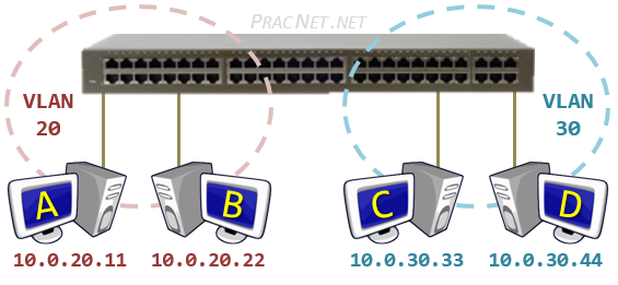
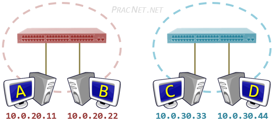
Despite all four hosts being connected to the same physical switch, the logical topology makes it clear that the hosts in VLAN 20 are unable to speak with the hosts in VLAN 30. Notice since there is nothing connecting the two “virtual” switches, there is no way for Host A to speak to Host C.
Since Host A and Host C are in different VLANs, it is also implied that they are in different Networks. Each VLAN will typically correspond to its own IP Network. In this diagram, VLAN 20 contains the 10.0.20.0/24 network, and VLAN 30 contains the 10.0.30.0/24 network.
The purpose of a Switch is to facilitate communication within networks. This works great for Host A trying to speak to Host B. However, if Host A is trying to speak to Host C, we will need to use another device – one whose purpose is to facilitate communication between networks.
If you’ve read the Packet Traveling series, then you know that the device which facilitates communication between networks is a Router.
A router will perform the routing function necessary for two hosts on different networks to speak to one another. In the same way, a Router is what we will need in order for hosts in different VLANs to communicate with one another.
There are three options available in order to enable routing between the VLANs:
- Router with a Separate Physical Interface in each VLAN
- Router with a Sub-Interface in each VLAN
- Utilizing a Layer 3 Switch
The remainder of this article will explore these three options and their configuration.
Router with Separate Physical Interfaces
The simplest way to enable routing between the two VLANs to simply connect an additional port from each VLAN into a Router.

The Router doesn’t know that it has two connections to the same switch — nor does it need to. The Router operates like normal when routing packets between two networks.
In fact, the process of a packet moving from Host A to Host D in this topology will work exactly as it does in this video. The only difference is since there is only one physical switch, there will only be one MAC address table – each entry includes the mapping of switchport to MAC address, as well as the VLAN ID number that port belongs to.
Each switch port in this diagram is configured as an Access port, we can use the range command to configure multiple ports as once:
Switch(config)# interface range eth2/0 - 2
Switch(config-if-range)# switchport mode access
Switch(config-if-range)# switchport access vlan 20

Switch(config)# interface range eth3/0 - 2
Switch(config-if-range)# switchport mode access
Switch(config-if-range)# switchport access vlan 30
Of course, before assigning the switchport to a VLAN, it is a good idea to create the VLAN in the VLAN Database.
The Router interfaces also use a standard configuration — configuring an IP address and enabling the interface:
Router(config)# interface eth0/2
Router(config-if)# ip address 10.0.20.1 255.255.255.0
Router(config-if)# no shutdown

Router(config)# interface eth0/3
Router(config-if)# ip address 10.0.30.1 255.255.255.0
Router(config-if)# no shutdown
Below you will find various show commands for the Router and the Switch, these can be used to understand and validate how the environment is functioning.
Router Show Commands
Router# show running-config
...
interface Ethernet0/2
 ip address 10.0.20.1 255.255.255.0
!
interface Ethernet0/3
 ip address 10.0.30.1 255.255.255.0
Router# show ip interface brief
Interface             IP-Address      OK? Method Status        Protocol
...
Ethernet0/2           10.0.20.1       YES manual up            up
Ethernet0/3           10.0.30.1       YES manual up            up
...
Router# show ip route
Codes: L - local, C - connected, ...

Gateway of last resort is not set

      10.0.0.0/8 is variably subnetted, 4 subnets, 2 masks
C        10.0.20.0/24 is directly connected, Ethernet0/2
L        10.0.20.1/32 is directly connected, Ethernet0/2
C        10.0.30.0/24 is directly connected, Ethernet0/3
L        10.0.30.1/32 is directly connected, Ethernet0/3
Router# show arp
Protocol  Address          Age (min)  Hardware Addr   Type   Interface
Internet  10.0.20.1               -   aabb.cc00.0220  ARPA   Ethernet0/2
Internet  10.0.20.11              2   0050.7966.6800  ARPA   Ethernet0/2
Internet  10.0.20.22              5   0050.7966.6801  ARPA   Ethernet0/2
Internet  10.0.30.1               -   aabb.cc00.0230  ARPA   Ethernet0/3
Internet  10.0.30.33              4   0050.7966.6802  ARPA   Ethernet0/3
Internet  10.0.30.44              4   0050.7966.6803  ARPA   Ethernet0/3
Router# show cdp neighbors
Capability Codes: R - Router, S - Switch, I - IGMP, B - Source Route Bridge
...
Device ID        Local Intrfce     Holdtme    Capability  Platform  Port ID
Switch           Eth 0/3           126             R S I  Linux Uni Eth 3/0
Switch           Eth 0/2           126             R S I  Linux Uni Eth 2/0
Switch Show Commands
Switch# show running-config
...
vlan 20
 name RED
!
vlan 30
 name BLUE
...
interface Ethernet2/0
 switchport access vlan 20
 switchport mode access
!
interface Ethernet2/1
 switchport access vlan 20
 switchport mode access
!
interface Ethernet2/2
 switchport access vlan 20
 switchport mode access
!
interface Ethernet3/0
 switchport access vlan 30
 switchport mode access
!
interface Ethernet3/1
 switchport access vlan 30
 switchport mode access
!
interface Ethernet3/2
 switchport access vlan 30
 switchport mode access
Switch# show mac address-table
          Mac Address Table
-------------------------------------------

Vlan    Mac Address       Type        Ports
----    -----------       --------    -----
  20    0050.7966.6800    DYNAMIC     Et2/1
  20    0050.7966.6801    DYNAMIC     Et2/2
  20    aabb.cc00.0220    DYNAMIC     Et2/0
  30    0050.7966.6802    DYNAMIC     Et3/1
  30    0050.7966.6803    DYNAMIC     Et3/2
  30    aabb.cc00.0230    DYNAMIC     Et3/0
Total Mac Addresses for this criterion: 6
Switch# show vlan brief

VLAN Name                        Status    Ports
---- --------------------------- --------- --------------------
...
20   RED                         active    Et2/0, Et2/1, Et2/2
30   BLUE                        active    Et3/0, Et3/1, Et3/2
...
Switch# show cdp neighbors
Capability Codes: R - Router, S - Switch, I - IGMP, B - Source Route Bridge
...
Device ID        Local Intrfce     Holdtme    Capability  Platform  Port ID
Router           Eth 3/0           152              R B   Linux Uni Eth 0/3
Router           Eth 2/0           166              R B   Linux Uni Eth 0/2
Router with Sub-Interfaces
The previously described method is functional, but scales poorly. If there were five VLANs on the switch, then we would need five switchports and five router ports to enable routing between all five VLANs
Instead, there exists a way for multiple VLANs to terminate on a single router interface. That method is to create a Sub-Interface.
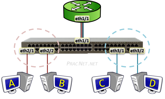 A Sub-Interface allows a single Physical interface to be split up into multiple virtual sub-interfaces, each of which terminate their own VLAN.
Sub-interfaces to a Router are similar to what Trunk ports are to a Switch – one link carrying traffic for multiple VLANs. Hence, each router Sub-interface must also add a VLAN tag to all traffic leaving said interface.
The logical operation of the Sub-interface topology works exactly as the separate physical interface topology in the section before it. The only difference is with Sub-interfaces, only one Router interface is required to terminate all VLANs.
Keep in mind, however, that the drawback with all VLANs terminating on a single Router interface is an increased risk of congestion on the link.
The Sub-interface feature is sometimes referred to as Router on a Stick or One-armed Router. This is in reference to the single router terminating the traffic from each VLAN.
The Switch’s port facing the router is configured as a standard Trunk:
Switch(config)# interface eth1/1
Switch(config-if)# switchport trunk encapsulation dot1q
Switch(config-if)# switchport mode trunk
The Router’s configuration of Sub-interfaces is fairly straight forward. First, we enable the physical interface:
Router(config)# interface eth1/1
Router(config-if)# no shutdown
Next, we create and configure the first Sub-interface:
Router(config)# interface eth1/1.20
Router(config-subif)# encapsulation dot1Q 20
Router(config-subif)# ip address 10.0.20.1 255.255.255.0
Apart from using the Sub-interface distinguisher (eth1/1.20) and using the encapsulation dot1q <VLAN#> command, the rest of the interface configuration is exactly the same as any other regular physical interface.
Similarly, we will also configure the Sub-interface for VLAN 30:
Router(config)# interface eth1/1.30
Router(config-subif)# encapsulation dot1Q 30
Router(config-subif)# ip address 10.0.30.1 255.255.255.0
A point of clarity regarding the Sub-interface syntax. The number after the physical interface (fa0/3.20 and fa0/3.30) simply serves the purpose of splitting up the physical interfaces into Sub-interfaces. The number specified in the encapsulation dot1q vlan ## command is what actually specifies what VLAN ID# the traffic belongs to.
These two values do not have to match, but often they do for the purpose of technician sanity.
Below you will find various show commands for the Router and the Switch. These can be used to understand and validate how the environment is functioning.
Router Sub-Interface Show Commands
Router# show running-config
...
interface Ethernet1/1
 no ip address
!
interface Ethernet1/1.20
 encapsulation dot1Q 20
 ip address 10.0.20.1 255.255.255.0
!
interface Ethernet1/1.30
 encapsulation dot1Q 30
 ip address 10.0.30.1 255.255.255.0
Router# show ip interface brief
Interface             IP-Address      OK? Method Status        Protocol
...
Ethernet1/1           unassigned      YES NVRAM  up            up
Ethernet1/1.20        10.0.20.1       YES manual up            up
Ethernet1/1.30        10.0.30.1       YES manual up            up
...
Router# show ip route
Codes: L - local, C - connected, ...

Gateway of last resort is not set

      10.0.0.0/8 is variably subnetted, 4 subnets, 2 masks
C        10.0.20.0/24 is directly connected, Ethernet1/1.20
L        10.0.20.1/32 is directly connected, Ethernet1/1.20
C        10.0.30.0/24 is directly connected, Ethernet1/1.30
L        10.0.30.1/32 is directly connected, Ethernet1/1.30
Router# show arp
Protocol  Address          Age (min)  Hardware Addr   Type   Interface
Internet  10.0.20.1               -   aabb.cc00.0211  ARPA   Ethernet1/1.20
Internet  10.0.20.11              0   0050.7966.6800  ARPA   Ethernet1/1.20
Internet  10.0.20.22              0   0050.7966.6801  ARPA   Ethernet1/1.20
Internet  10.0.30.1               -   aabb.cc00.0211  ARPA   Ethernet1/1.30
Internet  10.0.30.33              0   0050.7966.6802  ARPA   Ethernet1/1.30
Internet  10.0.30.44              0   0050.7966.6803  ARPA   Ethernet1/1.30
Router# show cdp neighbors
Capability Codes: R - Router, S - Switch, I - IGMP, B - Source Route Bridge
...
Device ID        Local Intrfce     Holdtme    Capability  Platform  Port ID
Switch           Eth 1/1           150             R S I  Linux Uni Eth 1/1
Switch Trunk Show Commands
Switch# show running-config
...
vlan 20
 name RED
!
vlan 30
 name BLUE
...
interface Ethernet1/1
 switchport trunk encapsulation dot1q
 switchport mode trunk
!
interface Ethernet2/1
 switchport access vlan 20
 switchport mode access
!
interface Ethernet2/2
 switchport access vlan 20
 switchport mode access
!
interface Ethernet3/1
 switchport access vlan 30
 switchport mode access
!
interface Ethernet3/2
 switchport access vlan 30
 switchport mode access
Switch# show mac address-table
          Mac Address Table
-------------------------------------------

Vlan    Mac Address       Type        Ports
----    -----------       --------    -----
   1    aabb.cc00.0211    DYNAMIC     Et1/1
  20    aabb.cc00.0211    DYNAMIC     Et1/1
  30    aabb.cc00.0211    DYNAMIC     Et1/1
  20    0050.7966.6800    DYNAMIC     Et2/1
  20    0050.7966.6801    DYNAMIC     Et2/2
  30    0050.7966.6802    DYNAMIC     Et3/1
  30    0050.7966.6803    DYNAMIC     Et3/2
Total Mac Addresses for this criterion: 7
Switch# show vlan brief

VLAN Name                        Status    Ports
---- --------------------------- --------- -------------------
...
20   RED                         active    Et2/1, Et2/2
30   BLUE                        active    Et3/1, Et3/2
...
Switch# show interfaces trunk

Port        Mode             Encapsulation  Status        Native vlan
Et1/1       on               802.1q         trunking      1

Port        Vlans allowed on trunk
Et1/1       1-4094

Port        Vlans allowed and active in management domain
Et1/1       1,20,30

Port        Vlans in spanning tree forwarding state and not pruned
Et1/1       1,20,30
Switch# show cdp neighbors
Capability Codes: R - Router, S - Switch, I - IGMP, B - Source Route Bridge
...
Device ID        Local Intrfce     Holdtme    Capability  Platform  Port ID
Router           Eth 1/1           136              R B   Linux Uni Eth 1/1
Layer 3 Switch
The last option for routing between VLANs does not involve a router at all. Nor does it involve using a traditional switch.
Instead, a different device entirely can be used. This device is known as a Layer 3 Switch (or sometimes also as a Multilayer switch). But exactly what is a Layer 3 switch?
 A Layer 3 Switch is different from a traditional Layer 2 Switch in that it has the functionality for routing between VLANs intrinsically. In fact, when considering how a L3 Switch operates, you can safely imagine that a Layer 3 Switch is a traditional switch with a built in Router.
With regard to VLANs the Multilayer switch is configured mostly the same way as a regular L2 switch:
MultilayerSwitch(config)# vlan 20
MultilayerSwitch(config-vlan)# name RED
MultilayerSwitch(config)# vlan 30
MultilayerSwitch(config-vlan)# name BLUE

MultilayerSwitch(config)# interface range eth2/0 - 2
MultilayerSwitch(config-if-range)# switchport mode access
MultilayerSwitch(config-if-range)# switchport access vlan 20

MultilayerSwitch(config)# interface range eth3/0 - 2
MultilayerSwitch(config-if-range)# switchport mode access
MultilayerSwitch(config-if-range)# switchport access vlan 30
Then, for each VLAN that you want the Multilayer switch to route for, you have the option of configuring an IP address within what is known as an SVI, or a Switched Virtual Interface.
An SVI serves as the L3 termination point for each VLAN – aka, the way in or out of each VLAN. Another way of looking at it is that the SVI serves as the interface on the built-in Router of the Multilayer switch, allowing traffic from one VLAN to reach the built-in Router and be routed to another VLAN as necessary.
The configuration for an SVI involves two parts. First, enabling IP Routing; and Second, applying an IP address to the VLAN.
To enable IP Routing, use the following command:
MultilayerSwitch(config)# ip routing
IP Routing only needs to be enabled once. Some L3 switches come with it enabled by default. Applying the command while it is already enabled will not cause any harm, so if in doubt as to whether it is already enabled or not, simply applying it again is safe.
To apply an IP address to the VLANs, configure the SVI as follows:
MultilayerSwitch(config)# interface vlan 20
MultilayerSwitch(config-if)# ip address 10.0.20.1 255.255.255.0
MultilayerSwitch(config-if)# no shutdown

MultilayerSwitch(config)# interface vlan 30
MultilayerSwitch(config-if)# ip address 10.0.30.1 255.255.255.0
MultilayerSwitch(config-if)# no shutdown
The two configurations above will enable routing between VLAN 20 and VLAN 30. The hosts in each VLAN can use the IP addresses 10.0.20.1 and 10.0.30.1 as their default gateway (respectively).
When Host A sends a packet to Host B, the packet will be switched within the same VLAN – no L3 processing will occur.
When Host A sends a packet to Host C, the packet will be sent to the SVI to be routed to the other VLAN – all regular L3 processing will occur: the TTL will be decremented and the L2 header will be rewritten.
Multilayer Switch Configuration
MultilayerSwitch# show running-config
...
ip routing
...
interface Vlan20
 ip address 10.0.20.1 255.255.255.0
!
interface Vlan30
 ip address 10.0.30.1 255.255.255.0
MultilayerSwitch# show mac address-table
          Mac Address Table
-------------------------------------------

Vlan    Mac Address       Type        Ports
----    -----------       --------    -----
  20    0050.7966.6800    DYNAMIC     Et2/1
  20    0050.7966.6801    DYNAMIC     Et2/2
  30    0050.7966.6802    DYNAMIC     Et3/2
  30    0050.7966.6803    DYNAMIC     Et3/1
Total Mac Addresses for this criterion: 4
MultilayerSwitch# show vlan brief

VLAN Name                        Status    Ports
---- --------------------------- --------- -------------------
...
20   RED                         active    Et2/1, Et2/2
30   BLUE                        active    Et3/1, Et3/2
MultilayerSwitch# show ip route
Codes: L - local, C – connected, ...

Gateway of last resort is not set

      10.0.0.0/8 is variably subnetted, 4 subnets, 2 masks
C        10.0.20.0/24 is directly connected, Vlan20
L        10.0.20.1/32 is directly connected, Vlan20
C        10.0.30.0/24 is directly connected, Vlan30
L        10.0.30.1/32 is directly connected, Vlan30
MultilayerSwitch# show arp
Protocol  Address          Age (min)  Hardware Addr   Type   Interface
Internet  10.0.20.1               -   aabb.cc80.0200  ARPA   Vlan20
Internet  10.0.20.11              0   0050.7966.6800  ARPA   Vlan20
Internet  10.0.20.22              0   0050.7966.6801  ARPA   Vlan20
Internet  10.0.30.1               -   aabb.cc80.0200  ARPA   Vlan30
Internet  10.0.30.33              0   0050.7966.6803  ARPA   Vlan30
Internet  10.0.30.44              0   0050.7966.6802  ARPA   Vlan30
MultilayerSwitch# show ip interface brief
Interface         IP-Address      OK? Method Status        Protocol
...
Ethernet2/1       unassigned      YES unset  up            up
Ethernet2/2       unassigned      YES unset  up            up
...
Ethernet3/1       unassigned      YES unset  up            up
Ethernet3/2       unassigned      YES unset  up            up
...
Vlan20            10.0.20.1       YES manual up            up
Vlan30            10.0.30.1       YES manual up            up
Note: both sets of tabs and configuration above are from the same device. For the sake of organization, one set of tabs refer to the L3 functions and the other refers to the L2 functions.
Summary
This article discussed the three different options for Routing between VLANs. In each case, the hosts in communication behave exactly the same. In fact, the hosts have no visibility into how and what they are connected to.
Each strategy above has its own benefits and limitations. Hopefully at this point you have a good idea of the options available to enable communication between hosts on different VLANs.


nice post – thanks for these nuggets!
I really liked the detailed diagrams, the config examples and of course, the clear explanation. An excellent source for beginners in networking. Kudos!
Hi Hector, glad you liked the article! Thanks for the kind words.
Hi! I’m from Portugal. Congrats for the way you teaching. Very well explained and easily to understand. Thanks!
Can single host access multiple vlan using layer 2 switch without router ?
Hi Dhiraj. No, it can not. Recall that a single L2 switch with two VLANs is essentially like two physical switches that are not connected together — frames from one can not reach the other. If you need to wrap your head around it further, I would recommend this article.
It can in the scenario of virtualization. Imagine the host is a hypervisor and it has a virtual switch, in that case, the switch port on physical switch, that connects your virtual switch to physical switch needs to be configured as a trunk port.
The hypervisor here is not acting like a host. It may be a physical server, but you are connecting into the virtual switch.
The virtual hosts within the hypervisor are still subject to the same rules as any other hosts regarding VLANs: The vSwitch will not let two virtual hosts in different VLANs speak to each other without something performing routing between the two VLANs.
The answer Ed provided is true as long as the host has only a single interface and is connected to an access port for a single vlan.
However, it is possible to have a host with multiple physical interfaces, each connecting to access ports on two vlans. Or if connected to a trunk port, if the host is vlan-aware, it can connect to multiple vlans on its sub-interfaces on the trunk port.
Here’s an example using a Raspberry Pi with the the vlan package loaded. https://www.sbprojects.net/projects/raspberrypi/vlan.php
There are always exceptions =). Yes. A single host with two NIC’s can have each NIC in a separate VLAN. And of course, if the host is VLAN aware, you can configure a host’s single interface as a trunk and therefore become members of multiple VLANs using VLAN tagging.
Excellent post. The best ! Thank you.
You’re welcome!
Well expained, however, just a few questions since I am stuck in this same scenario. My question is;
How do I route between two different networks, I created subinterfaces in both routers and I can ping from network 10.0.0.0 to network 192.168.0.2 interface fa0/0 but I cannot ping the interface (which have subinterfaces) directly connected to the other LAN which is interface fa0/1. I used router rip, please help what am I missing in the configurations.
Thank you
Asi
Hi Asi,
It is hard to know without seeing the configuration and topology. But I think your routers don’t know of each other’s networks. This article can explain the details, but try comparing the
show ip routeof each router and ensure they know about each other’s networks.Beyond that, this is probably not the best place to ask for specific configuration troubleshooting. Try posting on Reddit’s CCNA or Networking forums.
GOOOOOOD
I really liked very nice
Thank you kindly. Your method has assisted with really understanding this Vlan communication environment.
I appreciate you a whole lot.
Really nice explanation. I was having some trouble understanding the SVI part. Could you share an example with MAC addresses of the ports and SVIs and show how the L2 header changes?
Hi Vishal, absolutely!
Host A has the IP address 10.0.20.11 and Host C has the IP address 10.0.30.33. These IP address will be the Source and Destination in the L3 header. Remember, L3 is responsible for end to end delivery, therefore this header will not change.
To understand the L2 header, we’ll have to take a look at the Multilayer Switch output. From the
show arpcommand (the arp tab) we learn the four MAC addresses that will be used in the process:Host A has a MAC address of 0050.7966.6800, and Host C has a MAC address of 0050.7966.6803. And…
The MAC address of SVI 20 is aabb.cc80.0200, and the MAC address of SVI 30 is aabb.cc80.0200 (it is common for all SVIs on a L3 switch to share the same MAC address).
That said, when the packet is just leaving Host A, the L2 source will be 0050.7966.6800, and the L2 destination will be aabb.cc80.0200. When the packet is just leaving SVI 30, the L2 source will be aabb.cc80.0200, and the L2 destination will be 0050.7966.6803.
L2 will accomplish the hop to hop delivery to move the packet through the entire path.
Hope this helps.
Thanks Ed.
thank you for explanation.
I have a question on the SVI.
I could do the SVI connection as per ur explanation. however, when I trunk it with second layer three switch. then I couldn’t ping each other from another layer three switch. why could this happen?
thank you
What does it mean eth2/1, eth0/1 ?
Those are simply the names of the physical interface ports on the Switch.
In Layer 3 Switch
Add “ip routing” for enable the option of routing, this is important for test the communication of the VLANs.
Didn’t see your comment until after I hit post. 🙂
I’ve updated the article with a note about enabling IP Routing. Thanks for pointing this out!
If the switch supports it, you can also simply enable ip routing
https://www.cisco.com/c/en/us/support/docs/lan-switching/inter-vlan-routing/41860-howto-L3-intervlanrouting.html
I’ve updated the article with a note about enabling IP Routing. Thanks for pointing this out! =)
Thanks. I understand the routing of vlans well!
wow.. Great article.. I have worked 4 years in networking domain and configured VLANs too.. But never understood the concept. This is an eyeopener for me. Thanks a lot for writing such a lovely article 🙂
Very clear and detailed explanation 🙂
thank you soooooo much
Hi, I’m from Uruguay, very clear, detailed articles, it help me a lot, congrats !!
Perfect, just one suggestion: It would be perfect to add also “show cdp neigh detail” to your article, because it would be very explanatory to see the output on switch (in the first scenario – router with sub-interfaces), how are IP addresses visible in the output. Also if L3 switch would have one access switch connected to it, it would be perfect to see “sh cdp neigh detail” on this access switch, how are IP addresses visible in the output. If someone know the answer, please post it :).
There is another problem to discussion, what with the native vlan, and when, why and where to change configuration for that (router – switch, L3switch – L2switch).
Hi Jana, good point about
show cdp neighbor detail. Hopefully after reading this article though, you can build these topologies yourself in GNS3/VIRL and find the output yourself =).As for the Native VLAN, it wouldn’t necessarily tie into which of the three methods for routing between VLANs you choose. The concept of the Native VLAN was discussed here.
Hi Ed,
I must say,you have done brilliant work , but I think there is a small error upper image logical and physical has to alternate 🙂
Hi Peter. I’m not sure I’m following. I think they are labeled correctly. Are you seeing something else?
Good informative post.
We have a problem with a 2nd switch we have added to the network. Core switch is L3 and the additional one is L3 too. We cannot get this 2nd/new switch to route from its vlan20 across to vlan20 on the other switch. We have port going from vlan1 to vlan1 on the switches. tried tagging the ports in vlan20 but that doesnt work.
How can we route the new switch vlan20 across to the other switch vlan20?
Thanks
Hi Gary. Glad you liked the post. Your question is very specific though, unfortunately this isn’t the right medium for that type of question. I would recommend the Network Engineering Stack Exchange or the Networking Sub Reddit.
Hi,
Please tell me do i need to enable ip routing cmd in L3 switch to enable routing between vlan 20&v Vlan 30 ?
Hi Rohan. Yes, you do need to enable ip routing. I have updated the article with a note discussing it. Thanks for pointing this out =)
Please update the HSRP topic with troubleshooting methods.
One of the simplest description of how connecting VLANs for beginners
Thank you
Very nice explanation in general. But I got some specific questions. The first is why do we need a VLAN field in the entry of MAC table when VLAN has been set up in the switch? Is it only useful for blocking traffic when broadcasting within a domain? The second is, given a layer 3 switch scenario, if two hosts in the same VLAN domain, like A and B, would like to communicate with each other, only the MAC table will be used for forwarding, right? Although they go through a TCP/IP stack. Thanks : )
> why do we need a VLAN field in the entry of MAC table when VLAN has been set up in the switch?
Consider it as a separate MAC address table for each VLAN. The MAC addresses in VLAN 10 are not “known” to the users in VLAN 20 (etc).
> if two hosts in the same VLAN domain, like A and B, would like to communicate with each other, only the MAC table will be used for forwarding, right?
Yes, correct =). They will operate exactly like the hosts in this article:
https://www.practicalnetworking.net/series/packet-traveling/host-to-host/
https://www.practicalnetworking.net/series/packet-traveling/host-to-host-through-a-switch/
Thanks for your reply : ) I am still a little bit confused about the first question. Since users in diff VLANs live in diff IP subnets, they should be able to judge that they are in diff domains before sending packets. Hence, in my point of view, the VLAN field seems useless in this scenario. And the only scenario in which this field would be useful should be preventing broadcast packets from leaking.
A host can not always be trusted to do the right thing. =)
Look at the output of “show mac-address table” in the third example. Host A has the MAC address
0050.7966.6800and is in VLAN 20. Host D is in VLAN 30 and has the MAC address0050.7966.6803. Being that these hosts are in different VLANs, we do NOT want them to speak directly to each other (without going through a Router, which may have security policies applied).If Host A were to craft a malicious packet with a destination MAC address of
0050.7966.6803, despite the switch having this MAC address in it’s MAC Table, since the entry belongs to VLAN 30, the switch will not forward it to Host D. It will instead act as if the switch did not have a matching entry in the MAC table and simply flood the frame out all ports in VLAN 20.An excellent counterexample. Thanks a lot. = )
I have ever seen the configuration file of a layer 3 switch in which some interfaces are also configured to be sub-interfaces. Does it mean that a layer 3 switch can be in a mixed mode with sub-interface and SVI in use? Thanks = )
Hi Ed,
Great explanation, thanks. Have a quick question. For routing, hosts need to configure the SVI as default gateway, or we have to enable routing protocol on SVI and hosts. Would enabling proxy arp remove the need for turning on routing protocol or configuring default gateway on hosts?.
Host A needs to talk to Host C, it sends out a arp request for host C’s IP address, can the layer 3 switch jump in and proxy for host C?
Thanks,
Rajesh
I just want to say Thank you very much for such efforts, The graphics and method is amazing, please keep the good work.
can I get explanation of encapsulation and decapsulation for HTTP or FTP request
Hello. The Encapsulation process is described in this article:
https://www.practicalnetworking.net/series/packet-traveling/osi-model/#encap-decap
That link shows the three application layers as simply creating a generic “DATA” payload. Each application populates that payload differently. I don’t have a write up about FTP, but I did write about the inner workings of HTTP in this answer on the Network Engineering Stack Exchange:
https://networkengineering.stackexchange.com/a/13464/3675
Hope it helps.
Thank you so much, this really helped me!!
Hi Vidath. You’re welcome! I’m glad this helped!
Hi! I am an aeronautical engineer trying to acquire a solid background in networking as well. This is undoubtedly the best explanation of communication among hosts belonging to different VLANs that I have seen so far. Many thanks!
Hi Marco, thank you for the kind words =) I’m so happy you enjoyed the content!
In scenario 1> where configured router on stick with 2 vlans on switch.
switch connected with 1 host on each vlan.
Switch vlan 10 – host 10.10.10.10 = Host A
Switch vlan 20 – host 20.20.20.20 = Host B
*Default gateway not configured on both hosts
In Scenario 2> below is connectivity with 2 Switches instead 1 switch
Host A (Vlan10) – Switch 1 – Router – Switch 2 – host B (Vlan 20)
*The default gateway is not configured on switches
——————Question below for both topologies —————————————————
What will happen when Host A sends packets (Broadcast) packet who is 20.20.20.20 Will router interface/interfaces receive that packet if yes what will be details of that packet and frame. will it reply with proxy-arp and connectivity will work?
In both cases, the Router may respond to the ARP request (i.e., do Proxy ARP). But Proxy ARP shouldn’t be depended on for routing.
Also, remember, Host A wouldn’t send a Broadcast for 20.20.20.20 unless it though the IP 20.20.20.20 was in it’s own network. This series will explain how hosts communicate with one another through Routers and Switches:
https://www.practicalnetworking.net/series/packet-traveling/packet-traveling/
I am literally blown away how smooth your content flows. It’s really easy to follow and I’m so glad I’ve found your website. I am learning CCNA from zero understanding or experience. Slowly going through the CCNA 200 -301 book and was struggling with understanding Router on a stick and SVIs. I’ve now understood that they are are two separate options which can be used, but most importantly I get what the SVIs are used for.
Thank you so so much for setting this website and providing this content.
Hey Saeed, thanks for the kind words =) I’m so happy you found my articles beneficial.
If you’re studying for CCNA, I put a list of all my CCNA related articles here:
https://www.practicalnetworking.net/index/ccna/
Hope it helps!
Ed, thanks so much for this. I am currently designing my home network around a refurbished Cisco Catalyst 3750. I want to set up several VLANs but only need communication between a small subset of that. I am planning on several SSIDs running to isolate the wireless devices even further (I hate Wi-fi). Anyway, how do I isolate the communications between VLANs without it bleeding over to other VLANs? Granted I am very new at this managed switch game.
Ed, solid article and used it to great effect to build a few VLANs at home for a lab setting. Quick question on the topic, if the original purpose of VLANs is to provide a logical separation between networks (or subnets), why would you want to perform routing between the VLANs? I can’t find any good real world examples of a network that has multiple VLANs with routing in between them.
Originally, applying security policies (like ACLs) could only done on Routers. Meaning if you wanted to filter traffic between two PCs, you had to force that traffic to go through a Router. This allows you to logically separate PC’s but allow some or limited communication between them. If you want zero communication between them, then you don’t need to enable Routing between them.
So to summarize:
* If you intend for two PC’s to have full communication, put them in the same VLAN
* If you want two PC’s to have no communication, put them in different VLANs.
* If you want two PC’s to have limited communication, put them in different VLAN, but enable Routing between VLANs and filter traffic as necessary on the Router
Hope it helps.
Hi Ed Harmoush, First of all I want to say my special thanks for your article. It is clearly described how to build different VLANS in a Cisco switch it self. Using Cisco packet tracer I practically did it it went well for Multilayer Switches, Layer 3 Switches. I wonder that How I solve this problem in Below layer 3 Switches till example Cisco 2900 series or 2800 series or 1800 series switches. Your solution will be highly appreciated. Thank you in advance. Looking forward to hear from you soon../Sisira
Thank you very much for the detailed explanation, i had a lot of doubts about vlans and svi, and with this post you made them clear to me. Really thank you so much <3
awesome post! Thanks. The layer 3 switch routing answered a question I’ve had for ages.
Love the diagrams AND the switch/router configs as well. makes it REALLY clear
I really loved it!. I need not to look for any other 100’s of sites!. Its all in one best and complete book!. I would say a Bible for me!. Thank you very much!!. Appreciate your knowledge and wisdom!!.
You’re welcome, Spoorthi =).
Hi,
Thanks for this topic. I always gets confused but when i read is straight forward and clear… just one question if you enable ip routingo on l3 switch you enable all vlans communication but is there any command to route just like 2 vlan from 5 vlans actually?
You’d have to both enable and Create SVIs to tell the L3 switch to route between VLANs. So in your example, if you only want two VLANs to Route, you’d only create those two SVIs. The remaining three VLANs would just act as regular L2 VLANs.
Impressive article Ed. Awesome explanatory skills !!
In your example regarding router’s sub-interfaces, just one question to shed light:
was this the Mac address : aabb.cc00.0211 of router’s physical port,
or switchport’s virtual port ( ie switch’s trunk port) ;
To be precise, if the Mac address aabb.cc00.0211 belonged to the Switch or the Router ?
Many Thanks
You’re welcome.
aabb.cc00.0211 is the MAC address of the Router sub-interfaces.
As a follow up, some Router platforms use the Router’s interface MAC for all it’s sub-interfaces (which is what occurred above). And other Router platforms generate a new MAC address for all sub-interfaces.
Switch MAC addresses are never used/involved in traffic passing through a switch. More details here: https://www.youtube.com/watch?v=AhOU2eOpmX0
wow , thank you ED !
Awesome youtubes , very bullet-sharp, that smashed right through my confusion barriers ;
I had the feeling it was router’s own interface , because as a “parent” it could spawn those sub-interfaces;
But I was doubtful, because the switch apparently could enable somebody else’ interface as a trunk port ( given aabb.cc00.0211 belonged to the router, not the switch ) ;
Then I realised something fundamental: that the switchport interface could become a trunk interface, even if the neighboring interface is not a trunk interface. Many thanks Ed for your time , and your extraordinary genius explanatory lessons. Always enjoy reading up your wisdom !!
I really enjoyed reading your materials !!!
You’re welcome Jenny. Glad you enjoy this content =). Congrats on finding the breakthrough “aha” moment you were looking for.
So, how would I configure a fiber ports then if I have a 2921 router and 3560 switch and I want to use fiber to move data between the 2 devices?
awesome and clear. Total newb question..but on the last pic of the show ip route….why does the subnet change to /32 on th SVI Gateway instead of /24. Thanks so much!!!
Hi JJ. Cisco adds two routes to the Routing Table when you create a L3 interface:
C        10.0.20.0/24 is directly connected, Vlan20

L        10.0.20.1/32 is directly connected, Vlan20
The “C” is the Directly Connected route and represents the actual subnet you configured. The “L” is the Local interface IP. The router uses this to “route” incoming packets to this IP address to the Router itself.
This occurs with each illustration’s “show ip route” command output in the article.
Hi Ed,
Great article, explained very well. Perhaps an idea for another article or series might be expanding on inter-vlan routing and RoaS with Firewalls.
I’d be interested in hearing your views and experiences of the speed vs security trade-off, multiple DMZ type vlans and scenarios of filtering and protecting backend databases, middle-tier applications, and front end web services. That may also open a can of worms into “Load Balancers”, “Application Delivery Controllers” and “Reverse Proxies” too.
Hi Chris, thank you!
I touch on RoaS in this article:https://www.practicalnetworking.net/stand-alone/routing-between-vlans/
As for all the other stuff (FWs, LBs, Proxies, etc…) I’ll add those to my ever growing list of things I”d like to one day create content for =)
In the mean time, feel free to pop into the discord if you want to discuss anything further: pracnet.net/discord
This is a very nice post, easy to understand and clearly. It helps me so much. Thanks!
Glad you enjoyed it, Jesse!
Damn, this is good explanation.
Thank you, Qtip =)
In the MLS scenario, I was looking at the ARP and MAC tables, and found myself wondering,…when the packet crosses vlans, don’t the SRC and DST MAC addresses have to be changed when the L2 header is rewritten? And if so, it seems there aren’t enough MACs known in the CAM table (like, the MACs that were previously representing the router interfaces are gone, for example) I’m confused about how this will work, with regard to that. (I’ll take a look at the hyperlink about L2 stuff that is posted)
The virtual router will indeed change the MAC address of the frame as it passes from packet to packet. (although, some platforms use a single MAC address for all SVIs).
In the
show mac address-tableoutput, I filtered the output to only show the lines where the hosts were connected. The local MAC addresses (for local interfaces/SVIs on the switch itself) were removed.But good catch with your comment =). That is showing you’re putting all the pieces together! ^_^
Hi, I must say I’m really impressed with your explanation, I read hundreds of articles to understand vlan but found nothing as detailed and simple as yours. But I have got a question, consider 3 esxi servers which needs to be connected to a physical switch through ethernet cables. There are three vlans, each esxi server is involved in all these three vlans. All three esxi servers and switch are on same network. How do I configure this in order to be able to ping between esxi servers?
As of now I created 3 vlans on the physical switch in switchport mode access and assigned them to 9 different switchports then connected to the servers with ethernet cable. I also enabled IP routing and configured SVI on all three vlans with an IP address on the same network, but ping between server failed. Please advise on what can be done, I’m new to this.
Hi John. Thank you for the kind words =).
If each ESXI server will host VMs on the three various VLANs, I would simply connect one cable to each ESXi server and configure it as a trunk port. You can continue to do Routing on a dedicated Router.
There are of course, 1000s of “what ifs” and oddities which would require something different. But from a generic stand point I’ll provide the above. If you want to pick it apart further, feel free to post it on Discord and someone might be able to help you.