Virtual Local Area Networks, or VLANs, are a very simple concept that has been very poorly defined by the industry.
This article will explain VLANs from a practical perspective. It will be framed around the two major functions of VLANs, and concluded with an explanation of the idea behind the Native VLAN.
Finally, at the end of the article is a two question comprehension challenge – if you can successfully answer these two questions, then you can consider yourself to fully understand the concept of VLANs — the topic of configuring VLANs will be covered in another article.
Two Major Functions of VLANs
Below is a network with three different physical switches. The switches facilitate communication within networks, and the Routers facilitate communication between networks.
Each switch above independently perform all the functions of a switch.
If each of these switches have 24 ports and only two are in use, then 22 ports are left wasted on each switch. Moreover, what if you need to replicate this network elsewhere and you do not have three physical switches to accommodate?
That is where the first major function of a VLAN comes into play: A VLAN allows you to take one physical switch, and break it up into smaller mini-switches.
Breaking up one Physical Switch into multiple Virtual Switches
Consider each circle on the switch below as its own mini-switch (or virtual switch). Each of these mini-switches are a collection of switch ports which operate completely independent from the others — exactly as they would had there been three different physical switches.
Traffic flow through the single switch of this topology operates exactly as it did in the topology above it with three separate physical switches. The routers are configured and operate exactly as they did above.
Each virtual switch, or VLAN, is simply a number assigned to each switch port. For example, the two switch ports in the red mini-switch might be assigned to VLAN #10. The two ports in the orange mini-switch might be assigned to VLAN #20. And lastly the two switch ports in the blue mini-switch might be assigned to VLAN #30.
Any switch port which is not explicitly assigned a VLAN number, resides in the default VLAN. Which for most vendors corresponds to VLAN 1.
Traffic arriving on a switch port assigned to one VLAN will only ever be forwarded out another switch port that belongs to the same VLAN – a switch will never allow traffic to cross a VLAN boundary. Again, each VLAN operates as if it were a completely separate physical switch.
In the first illustration, traffic from the red switch cannot magically appear on the orange switch without first passing through a router. Similarly, in the second illustration, traffic in VLAN #10 cannot magically appear on VLAN #20 without also passing through a router.
When a frame arrives on a switchport in VLAN #10, it can only leave a switchport in VLAN #10. You and I can see that the same frame is traversing all three VLANs, but from the Switch’s perspective, it is three different instances of a frame arriving on one port in one VLAN, and leaving on another port in the same VLAN.
VLANs and MAC Address Tables
By definition, a Switch is a device whose primary purpose is to move data within IP Networks. To accomplish this goal, every switch maintains a MAC Address Table, which is a mapping of the MAC addresses connected to every Switchport. A simple representation of a single entry in a MAC address table would be: MAC Address | Port.
A Switch which supports VLANs will also include the VLAN # for each entry of the MAC Address Table. A simple representation of a single entry in a MAC address table of a VLAN aware switch would be: VLAN# | MAC Address | Port.
In a way, it’s almost as if each VLAN maintains their own independent MAC address table. If Host A were to send a frame with a destination MAC address of Host B, that frame would still only be flooded solely to the switch ports in VLAN #10. Even if a MAC address table entry for Host B existed associated to VLAN #30.
Ultimately, assigning different ports to different VLANs allows you to re-use a single physical switch for multiple purposes. This is the first major function of a VLAN.
But that isn’t all VLANs allow you to do. The second major function is VLANs allow you to extend the smaller Virtual switches across multiple Physical switches.
Extending Virtual Switches across multiple Physical Switches
To illustrate this point, we will expand the topology above with an additional physical switch and two additional hosts:
Notice how a VLAN# 10 and VLAN# 30 have been extended onto a second switch. This enables Host A and Host C to exist in the same VLAN, despite being connected to different physical switches located in potentially different areas.
The primary benefit of extending a VLAN to different physical switches is that the Layer 2 topology no longer has to be tied to the Physical Topology. A single VLAN can span across multiple rooms, floors, or office buildings.
Each connected switch port in the topology above is a member of only a single VLAN. This is referred to as an Access port. An Access port is a switch port that is a member of only one VLAN.
When configuring a port as an Access port, the administrator also designates the VLAN number that port is a member of. Whenever the switch receives any traffic on an Access port, it accepts the traffic onto the configured VLAN.
In order to extend a VLAN to the second switch, a connection is made between one Access port on both switches for each VLAN. While functional, this strategy does not scale. Imagine if our topology was using ten VLANs, on a 24 port switch nearly half of the ports would be taken up by the inter-switch links.
Instead, there is a mechanism which allows a single switch port to carry traffic from multiple VLANs. This is referred to as a Trunk port. A Trunk port is a switch port that carries traffic for multiple VLANs.
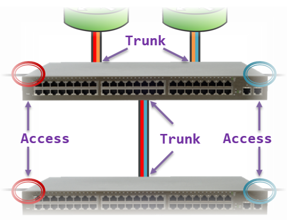
We can use Trunk ports to reduce the amount of switch ports required for the topology above. This enables us to leave more ports available to add hosts to the network in the future.
This physical topology operates (logically) identically to the illustration above it, but requires far fewer switch ports.
We were able to use a total of four Trunk ports (across both switches) to replace eight different Access ports in the prior illustration.
Typically, switch ports connected to end-host devices are configured as Access ports (e.g., workstations, printers, servers). Conversely, switch ports connected to other network devices are configured as Trunk ports (e.g., other switches, routers). We will uncover the reason for this later in this article.
Tagged Ports and Untagged Ports
A Trunk port on a switch can receive traffic for more than one VLAN. For example, in the illustration above, the link between the two switches is carrying traffic for both VLAN 10 and VLAN 30.
But in both cases, traffic is leaving one switch as a series of frames, and arriving on the other switch as a series of frames. Which begs the question, how will the receiving switch determine which frames belong to VLAN #10, and which frames belong to VLAN #30?
To account for this, whenever a Switch is sending frames out a Trunk port, it adds to each frame a tag to indicate to the other end what VLAN that frame belongs to. This allows the receiving switch to read the VLAN tag in order to determine what VLAN the incoming traffic should be associated to.
An Access port, by comparison, can only ever carry or receive traffic for a single VLAN. Therefore, there is no need to add a VLAN Tag to traffic leaving an Access port.
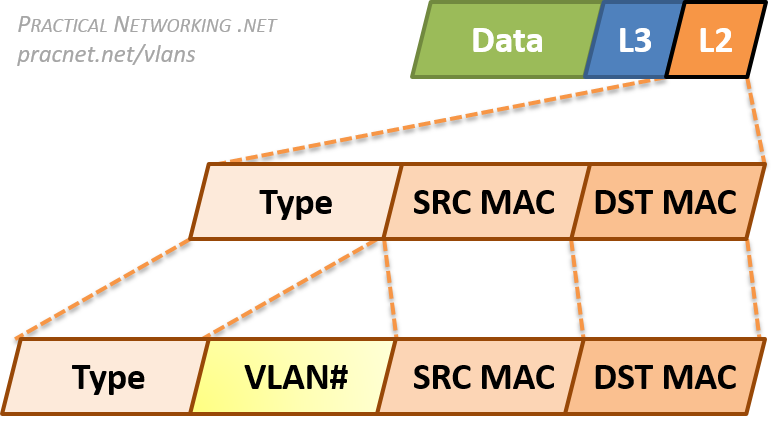
Since VLANs are a Layer 2 technology, the VLAN Tag is inserted within the Layer 2 header. The standard Layer 2 header in modern networks is the Ethernet header, which has three fields: Destination MAC Address, Source MAC Address, and Type.
When an Ethernet frame is exiting a Trunk port, the switch will insert a VLAN Tag between the Source MAC address and the Type fields.
This allows the receiving switch to associate the frame with the appropriate VLAN.
To summarize, the final topology with traffic traveling between Host C and Host D through Access ports and Trunk ports will look like this:
The physical topology above will work exactly like the logical topology below. The hosts will not know whether they are going through two physical switches (or three or four), or what VLANs they are in. They operate exactly as they would in any situation which involves moving packets through a network.
Access Ports and End-Host Devices
Earlier we mentioned Access ports typically face end-host devices like workstations or printers or servers.
Part of the reason for this is that switches do not add a VLAN tag when sending traffic out an Access Port.
This allows a host to operate without any knowledge of the VLAN they are connected to.
In a way, the hosts are, intentionally, completely blind to the existence or use of VLANs. Hosts simply send data on a network without any knowledge of VLANs, or the switches they might be connected to.
There was a point in the early days of Networking where certain end-devices would react negatively if they received a frame with a VLAN tag. For such systems, which were strictly expecting only the typical fields in an Ethernet header, the frames which included a VLAN tag might appear as a malformed Ethernet header.
However, this was rare, as the construction of the VLAN tag was intentionally designed to avoid being interpreted as a malformed frame (this will make more sense in the next section).
Either way, the general precedent is traffic to end-hosts should not include any VLAN tags, Hosts can and should remain blissfully ignorant of what VLANs they are in, or even whether VLANs are being utilized at all.
A possible exception would be if a single Physical Host is hosting multiple Virtual Machines (VMs) — like a Hypervisor. In some cases, each of those VMs need to exist in separate VLANs. Therefore, the Physical Host must be connected to a Trunk port, and must send and received VLAN tags in order to confine the virtual machine traffic to a specific VLAN.
Terminology
Finally, a quick note on terminology. The terms Access port and Trunk port are usually associated with the Cisco world. But VLANs are an open standard, therefore other vendors are able to implement VLANs as well.
What Cisco calls a Trunk port (i.e., a switch port that carries traffic for more than one VLAN), other vendors refer to as a Tagged port – referring to the addition of a VLAN tag to all traffic leaving such a port.
What Cisco calls an Access port (i.e., a switch port that carries traffic for only one VLAN), other vendors refer to as an Untagged port – referring to the traffic leaving the switch port without a VLAN tag.
These terms are not exhaustive, there are some vendors that may yet use other terminology, other vendors may even mix and match these terms. Regardless of the terminology used, all the concepts discussed above still apply.
802.1Q VLAN Tag
VLAN tags requires adding and removing bits to Ethernet frames. The specific sequence of bits to add is governed by an open standard, which allow any vendor to implement VLANs on their devices.
The exact format of the VLAN Tag is governed by the 802.1Q standard. This is an open, IEEE standard which is the ubiquitous method of VLAN tagging in use today.
To demonstrate exactly how the VLAN Tag modifies a packet, take a look at the packet capture below of the same frame before and after it exits a Trunk port.
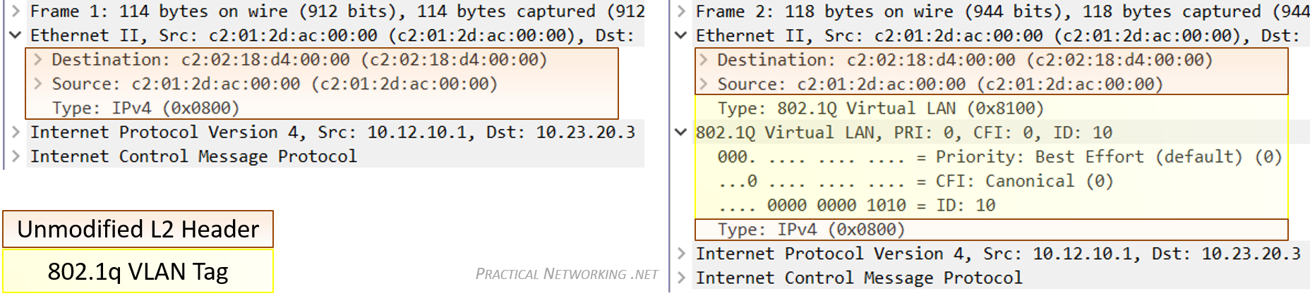
The portion of the frame highlighted in yellow is the added VLAN tag. Notice it is inserted between the Source MAC address and Type field of the original Ethernet header.
You can view this capture yourself in Cloudshark, or you can download the capture file and open it in Wireshark.
No other modification to the frame or its payload is made by the addition or removal of the VLAN tag. That said, since even the slight modification displayed above is made, adding and removing the VLAN tag also involves recalculating the CRC — which is a simple hash algorithm devised to detect transmissions errors on the wire.
There is an older method of VLAN tagging which is a closed, Cisco proprietary method. This method was called Inter-Switch Link, or ISL. ISL fully encapsulated the L2 frame in a new header which included the VLAN identification number.
But these days, even newer Cisco products do not support ISL, as the entire industry has moved to the superior, open standard of 802.1Q.
Native VLAN
There is one final concept associated with VLANs that often brings confusion. That is the concept of the Native VLAN.
The Native VLAN is the answer to how a switch processes traffic it receives on a Trunk port which does not contain a VLAN Tag.
Without the tag, the switch will not know what VLAN the traffic belongs to, therefore the switch associates the untagged traffic with what is configured as the Native VLAN. Essentially, the Native VLAN is the VLAN that any received untagged traffic gets assigned to on a Trunk port.
Additionally, any traffic the switch forwards out a Trunk port that is associated with the Native VLAN is forwarded without a VLAN Tag.
To see the Native VLAN in action on a live trunk port, check out this video.
The Native VLAN can be configured on any Trunk port. If the Native VLAN is not explicitly designated on a Trunk port, the default configuration of VLAN #1 is used.
That being said, it is crucially important that both sides of a Trunk port are configured with the same Native VLAN. This illustration explains why:
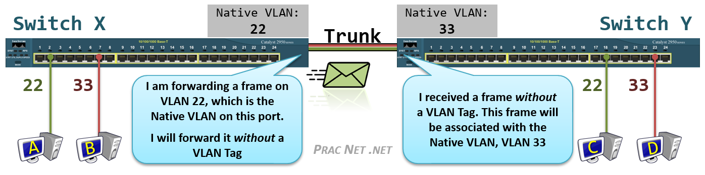
Above we have four Hosts (A, B, C, D) all connected to Access Ports in VLAN #22 or VLAN #33, and Switch X and Switch Y connected to each other with a Trunk port.
Host A is attempting to send a frame to Host C. When it arrives on the switch, Switch X associates the traffic with VLAN #22. When the frame is forwarded out Switch X’s Trunk port, no tag is added since the Native VLAN for the Trunk Port on Switch X is also VLAN #22.
But when the frame arrives on Switch Y without a tag, Switch Y has no way of knowing the traffic should belong to VLAN #22. All it can do is associate the untagged traffic with what Switch Y’s Trunk port has configured as the Native VLAN, which in this case is VLAN #33.
Since Switch Y will never allow VLAN #33 traffic to exit a VLAN #22 port, Host C will never get this traffic. Even worse, due to a Switch’s flooding behavior, Host D might inadvertently get the traffic that was destined to Host C.
Finally, it should be noted that the Native VLAN is an 802.1Q feature. The antiquated tagging mechanism of ISL simply dropped traffic receive on a Trunk port that did not include the ISL tag. Also, remember that the Native VLAN concept only applies to Trunk ports — traffic leaving and arriving on an Access port is always expected to be untagged.
VLAN Comprehension Challenge
To test yourself to see if you fully understand how VLANs work, there is a simple challenge we can offer.
Below is a (poorly) configured topology, featuring five switches and twelve hosts. Each switch port is configured as either an Access port in the displayed VLAN, or a Trunk Port with the Native VLAN displayed.
The challenge is to answer just these two simple questions:
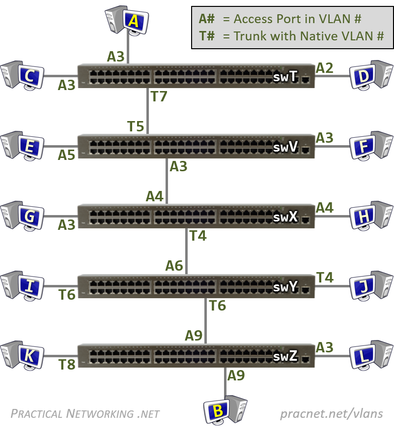
Question #1:
If Host A sends a frame to Host B, will Host B receive it?
Question #2:
If Host A sends a Broadcast, which hosts will receive it?
Prefer to consume this article in Video form? If so, check out this video on Youtube:


perfect explanation.Would be great if you could explain NAT.
Glad you enjoyed it, Vasu! How did you do with the VLAN Challenge?
NAT is actually the topic of the current article I am working on. So that is coming soon… stay tuned 😉
Update: NAT Article series has been released! Check it out here: pracnet.net/nat
very nicely explained..pls let me know if you have explained BGP!!
Hi Sushant. I’ve released one article on BGP so far. It discusses the BGP oldest path attribute. I’m sure I’ll write others. In the mean time, if you want to learn more about BGP, check out the BGP Class on the Classes page.
Yeah! Come join us in Dallas the week of 09/24. The Cisco BGP class is awesome. There’s also a virtual component to that session that would allow you to attend remotely. That class works great as a virtual session. Hope to see you!
This is brilliant! Nothing more to add, nothing to remove. So far these are the best presented articles I’ve ever seen. I thank you on behalf of all networking newbies for making the effort to create this website! Looking forward to read more.
Ves
Hi Ves, I’m happy to hear they help! Comments like this are great encouragement to keep working on more articles. Thanks for the note!
Yes Ed, I have never seen such simple explanations for vlans thank you so much..
Wow this information was so easy to understand! I went through 4 years of school and still did not have a firm grasp on what exactly a VLAN was. Found this article on spiceworks and im glad i did. will be passing along to others for enlightenment =)
Hi Jon, glad you found it useful! I appreciate you passing the article along!
How is possible to got different native vlan on both sides of trunk link?
Native vlan mismatch?!?
Exactly. The Native VLAN configuration only applies to the local switch (and even further, the local switch’s interface). Nothing is stopping you from (inadvertedly) connecting two switches and configuring two different Native VLANs. The Native VLAN is not shared or negotiated between the switches, it is statically set.
Some Cisco switches and code versions will use CDP to share with one another what they have configured as the Native VLAN, so you can some times get warnings that you have a Native VLAN mismatch.
But ,Packet will be dropped right (as explained in section Native Vlan ) Then how come in question 2
switch V receives VLAN packet with vlan id as 3(as Trunk native vlan is 7) so switch V should receive packet with vlan id 7
no ??
I am confused here ,As answer to question 2 says “Switch V considers the frame in VLAN #3” .
how ??
Switch V will consider untagged frames coming in on the trunk port as a frame in VLAN #5 (the Native VLAN of that trunk port).
However, in this exercise it is a tagged frame in VLAN #3. So the concept of the Native VLAN does not apply for this specific frame.
Thanks, Wim 😉
why is it tagged as VLAN #3? and Not VLAN #7?? Whenever data leaves a switch’s trunk port, it is tagged with the switch’s Native VLAN so long as the data was received untagged and in this case Host A forwarded the data frame untagged. Could you please explain this step?
Host A forwarded the frame untagged, but it was received on an Access Port in VLAN 3… therefore, all received traffic on that port is considered to be a part of VLAN 3.
thank you for taking the time to create an article like this. you have discussed the topic in a clear and concise manner. will pass this along.
Hi Sheree Ann, glad you enjoyed it! Thank you for the shares!
This is great, really well explained. I notice that you have some classes listed…are these the articles, or is there something else that offer ? Because I am already sold on your material 🙂
Hi James! Glad you enjoyed the articles.
The classes do cover some of the topics on the articles, but in all cases go into more depth. The animations are also more “one step at a time” in the classes, to ensure each student fully comprehends the order of things and what happens next, as well as why.
The classes also cover a far bigger spectrum of technologies. Shoot me an e-mail if you want to know more: [email protected].
I thought the only way to connect 2 switches together is using a Trunk Port. The port that connects Switch V and Switch X is an Access port, according to your diagram. How can the frame continue onto the next switch through an Access port?
That is the only common best practice way, but you can absolutely connect two switches together using access ports. The second switch would only be able to connect hosts in that single VLAN, of course, so if you are simply trying to add more switchports for a particular VLAN, using an access port inter-link is a perfectly appropriate solution.
so in your third diagram above you show a link to vlan 10 in two switches via an access port (and one with vlan 30)…from that i had the impression that the access ports had to be configured using the same vlan. But based on your challenge problem as Adam mentioned Switch V’s access port vlan3 and Switch X’s access port vlan4 doesn’t have to match?
is this poor practice to do it this way
The Access or Trunk configuration is on a per switch-port basis. So yes, in a properly designed network they should match, but nothing is enforcing that they match — so it can absolutely happen in a misconfigured network.
And the VLAN challenge intentionally has the configurations not match to test your knowledge and understanding of VLANs. By no means should it be used as an example of a well designed network =).
It is great document, it clear lots of my doubts.
There is one question, in switch packet(pck) lookup will happen based on destination mac address(dmac) and if we are not finding out a entry for dmac, we will flood a pcks on all ports in same vlan.
Now consider we sent pck from host A to switch T through access vlan 3. This pck is not tagged with vlan 3. How does switch CPU will find out pck comes on vlan 3 ?
Are switches do tagging internally on access port for ingress pck and remove tagging while egress pck?
Because there are multiple pck are ingress/egress from switch ports and they might tag or untag, there should be some way to find out switch cpu which pck comes from which vlan 🙂 ?
Thanks,
Rohit
The port Host A is connected to is configured as an Access port in VLAN 3, therefore, any packets sent by Host A will be considered by the switch to be in VLAN 3. This will happen if Host A includes or doesn’t include a VLAN tag (typically it will not include a VLAN tag). If Host A had tagged the packet with a different VLAN, then the switch would have dropped the packet.
So yes, in a way, there is an internal tagging of packets by the switch.
Great article!
Excellent explanations. I used this as guide for fresh IT guys assigned to implement a VLAN in a lab enviroment and they did it perfectly with the help of this explanation
this is the best and most simple explanation so far~ thanks ~~ it really help me a lot~
I feel like a 6 yr old after reading this artical>
Excellent tutorial with exercise. It is one of the best resources available on net. I passed CCNA but I never seen such neat material. If there is a book available on networking fundamentals from your site, I definitely buy it.
Thanks for the kind words. I’ve published a Networking Fundamentals series. Details here:
https://www.practicalnetworking.net/index/networking-fundamentals-how-data-moves-through-the-internet/
Wow, thank you for putting together, very easy to understand!
this is the best explanation about VLAN so far. it is easy to understand!
Really awesome, thanks! Would love to see a “well designed” topology for comparison at the bottom, and maybe more questions with a different network. But agree with the other comments, best explanation I’ve seen.
Very helpful article. Got very clear understanding of VLAN and related terms. Thank you so much.
Really wish I had these nicely laid out articles and clean GIFs back in my day for the CCNA haha. Very well done article on VLANs and especially inter-vlan routing.
Best approach to teach this important topic: First explains (very well) what you can do and then you’ll be able to plan whatever your need. Other sites elaborate complex todo lists targeting the most common setups. Liked also how the hyperlinked terms can help newbies and so kept the text short. Thanks !
I’m a little confused about the Native vlan. Is the native vlan the same as the default vlan, only if the default vlan is changed from vlan 1 ? You have to tell the trunk port what the default vlan is? The only reason a trunk port would receive an untagged frame is if the port wan’t in a vlan.
All ports start in the default vlan 1, which is untagged. If you set up a single vlan, then you have to setup a trunk port, but only only the vlan you setup gets tagged, the default vlan is still untagged. You can’t assign a trunk port a native vlan that doesn’t exist, so the native vlan is the default vlan, unless you’ve changed the default vlan to be something other than vlan 1. Is my thinking wrong about this?
Also, computers on a vlan are isolated, but they still need a default gateway (router) if they want to connect to the internet. Computers in vlan 1 can still connect to computer in vlan 2 because they are connected to a router, and a router knows all networks to which it is connected. What if you didn’t want vlan 1 to communicate with vlan 2 ? But all computers still need internet access. For example, in your 2nd diagram, what if you didn’t want computer A to communicate with computer B, but they both needed to connect to the internet using the router they are attached to.
Hi Brian,
I think you are confusing a few terms, namely Native VLAN vs Default VLAN vs Default Native VLAN. I would recommend reading this post to help highlight the differences.
Regarding your second question, you could use an Access-List to selectively Permit or Deny traffic.
All it can do is associated the untagged traffic with what Switch Y’s Trunk port has configured as the Native VLAN, which in the case is VLAN #33.
Got some typos to fix here. It should read as: “All it can do is ASSOCIATE” and “which in THIS case is.”
Good catch. Fixed. Thanks!
Hi Ed, this is probably one of the most detailed, intuitive and easily understood VLAN explanation on the web, and with the comparison of tagged/untagged vs access/trunk terminology, it clears a lot of confusion.
Would be really great if you can expand this to IP phones that have LAN and Data ports, and explain how frames coming in and out of the IP phones and data ports works.
Thanks once again. Cheers.
Hi Arthur, thanks for the kind words! Really happy you enjoyed the article!
Great suggestion. In fact, I have an outlined already written for an article that will cover Auxillary (Voice VLANs) and how all that works. I’m afraid I don’t have a timeline at this point for when I will get to writing it. Working on a Subneting video series at the moment (they are going to be great!).
Hey Ed,
I am CCNA certified and yet I have not seen or read such neat explanations ANYWHERE. You are doing a fantastic job. Ed, when is the subnetting video series coming out? Eagerly waiting for it.
Thanks
Arjun.
I could not stop myself writing this comment. Simple yet Perfect explanation. I’ve been looking for this. Thank you.
You’re welcome!
Awesome Ed…you completely nailed it…I have a better understanding now and would go back to an abandoned tshoot project I had on gns3. Thanks
Glad you enjoyed it, John =) Good luck with the TSHOOT project =)
this challenge question is so helpful…it really forces you to understand vs broader overview without understanding which is all these youtube videos ever do
Glad you found it helpful, Danimal =). Thank you for the read.
I have been working in networking field from last 3.5 years and always had doubts regarding Native VLAN. This is the first time I have seen an article explaining VLAN in such an easy way. I have read your other articles as well such as Gratuitous ARP and came to know that ARP scope is a different concept which is mostly termed as GARP only on other websites.
You Are The Best 🙂
Hi Mehak. Glad you enjoyed the articles =). I’m sure you have colleagues that would also enjoy them, please consider sharing these articles with them if so =).
Do you have any articles published regarding TCP? There are few classes for Network fundamentals on your website. However I am looking for TCP explained in articles like above VLAN topic.
Let’s just say, TCP is on my list. Currently I’m working on a Subnetting video series… they are going to be top notch.. stay tuned =)
Yeah I already did!
I was so fascinated by the explanation that I immediately shared
the link with my friends.
Thank you for the shares, I appreciate it!
Also it will be grateful if you publish articles on SSL(Its only under classes tab).
Looking forward to read more articles on SSL and TCP published by you.
On your first illustration, why is it not practical to daisy chain the switches instead rather forwarding to a router? Same as daisy chain a router? Is it because of the host IPs availability? If connecting to another network, will one router suffice?
Just started reading about networking recently. Thanks!
Hi John.
Because each of the “dashed circles” represents a different IP Network. Switches only facilitate communication within networks. You would need Routers in between to facilitate communication between networks.
If the whole topology was a single IP Network, then the three daisy chained switches would absolutely work.
The purpose of having multiple networks is to separate groups of communicating devices within their respective purposes. For instance, a school might have a different IP Network for each classroom.
Thank you such a detailed explanation.
I have a doubt:
Router is required for 2 hosts to communicate with each other that are in 2 different VLANs. However in the above challenge, Host A (VLAN 3) was able to send the packet to Host B(VLAN 9) without router/ layer 3 switch by only adding and removing VLAN tags as per the configuration.
You have mentioned that is a poorly configured topology however is it also another way of communication between 2 hosts of different VLAN without using any router?
Hi JKC,
Typically, when you have multiple VLANs, you also have multiple IP Networks. That is the “correct” way of doing things. A Router is required to communicate between IP networks.
That said, often the VLAN is the boundary between different Networks, so it is often said that a Router is needed to communicate between different VLANs. That statement is true, but isn’t the whole truth — in reality, the Router is needed because you are talking between IP networks.
Remember, a VLAN configuration is purely local to the switch. In the VLAN Challenge, Switch T has no clue how Switch Z is configured (or any other switch). All the hosts in the VLAN Challenge are configured with an IP address in the same IP Network. So while traffic between Host A and Host B are crossing different VLANs, they are never crossing different IP networks — hence, no Router is needed.
But, surely, if they are using the same IP network address, they can’t be separate VLANs – they are part of the same VLAN?
Remember, the configuration of VLANs is Layer 2, and the configuration of IP and IP Networks is Layer 3. There is nothing stopping you from configuring different IP networks in the same VLAN, or the same IP network in different VLANs.
Of course, neither of those options are considered “best practice”.
So it isn’t that they can’t be in separate VLANs, it is that they shouldn’t.
Hi Ed
I have the question as Daniel’s. It actually occurred to me after I had already posted a praiseful comment for this tutorial, which is great. However, I don’t think this network functions at all. I found this thread after checking to see if anyone else has asked this question. I actually implemented a simple network in Packet Tracer to test the idea. I wish I could attach a file or a screenshot here. Here’s the diagram:
PC1 (192.168.0.2) —SW1(F0/1, A2) — SW1(F0/2,T2) — SW0(F0/2,T1) — SW0(F0/1, A1)— PC0 (192.168.0.1)
When I ping from one PC to the other, ARP requests are dropped by the first switch on the path.
I would wager this is more a packet tracer nuance than an actual switch. I’ve tested this topology using GNS3 and similar concepts using actual switches, all have functioned as described in the article. I suggest trying the same set up in GNS3/EVE-NG and see how it plays out.
PS: Did you disable CDP between the switches? And did you make sure a trunk actually formed. Often (particularly with packet tracer) mismatched VLANs will prevent the trunk from forming. Probably a good idea to disable DTP entirely as well.
Thank you for the informative article and response! Doyou accept donation by chance?
Hi John,
That is kind of you to offer. At the moment I do not have a system set up to accept donations. In the future I’ll be offering e-learning classes. You’re welcome to “donate” by purchasing one of those.
In the mean time, I’m happy just knowing you enjoyed the content. Thank you for the consideration of a donation.
Most easiest way to understand with graphics and easy descriptions….it was my first article reading here….I will start reading others now
Hi Pranav, glad you enjoyed them =) Welcome to the site!
As far as this very subject matter is concerned, no other material need exist on the net. Cleared every shade of doubt.
Wow, thanks for the kind words, Okey! That was exactly my goal =)
Awesome article, Ed. I reversed the flow from B to ensure all the switches would even know B’s MAC address and, sure enough, a single broadcast from B would have propagated all the way to Switch T and even out to Device A, making certain that a path from A to B’s unicast MAC would be predicated on forwarding and not one instance of flooding. Great job!
Hey Toby =) Glad you liked it! And thanks for confirming it works as explained with a lab. I’ll bet that was a fun one to build out 😉
Thanks alot, Ed ! your articles are perfect for networking newbies like us. please keep them coming. containers please ? 🙂
very nicely explained. Can you please add tutorials on TCP/IP Reference model, TCP, UDP, and IP layers/protocols/headers?
It would be great if you add tutorials on some of the network services like DNS, DHCP, SNMP etc. and What happens when you type an URL (ex: google.co.in) in the browser and press enter?
Thank you in advance .
Hi Ed,
This explanation and exercises are awesome. This article helped me a lot in a network troubleshooting for a firewall deployment. Thanks a lot, guy.
Thank you, your work is amazing, these concepts are so clear to me now.
Please do a series on VXLAN too! Thanks a million.
thank you thank you thank you for explaining it so well…..i couldnt answer the challenges first time but with your explanation I feel like i understood alot! Thank you again
switch t is configured with native vlan 7 and switch v is configured with native vlan 5.this configuration would generate native vlan mismatch and stp will put the port in inconsistent state.so in this case host a cannot communicate host b
Hi Ganesh, that is only the case if you are using Cisco switches with CDP enabled. Either way, that is outside the scope of what this article was trying to communicate. The challenge is merely an exercise to determine if you understand how frames flow through a L2 path in reguards to VLANs and VLAN tagging.
The connection between two switches using an access port and a trunk port like the switch X and Y, Y and Z will give us limited connectivity because only VLAN 1 is allowed. How is possible to do this exercise without this consideration?
Hi Hasser, I would encourage you to configure the topology in a lab and test it out yourself. It does work as stated 😉
First of all , Thanks for this simple informative great Explanation .. please keep going 🙂
But i have a question regarding Native Vlan Mismatch draw , what if Host B tries to send traffic to either Host C or D .. As i’ve understood from your explanation that the frame will reach Switch Y tagged with Vlan 33 and this will match the native Vlan on the trunk port too , so it supposed to strip off the tag and the frame exits the trunk port untagged , But how the switch will handle that ? ,, Will it drop the traffic or forward it to the default Vlan for example ? this is a little bit confusing to me. Hope to here from you soon as i tried to search for this scenario result but in vain.
Hi Mahmoud, glad you enjoyed the explanations.
When Switch Y receives a frame tagged with VLAN33, it will simply accept the traffic on to VLAN33 and deliver the frame to Host D.
Remember the Native VLAN determines what VLAN a frame without a tag is associated to. If a frame arrives with a tag, the frame is accepted on to the VLAN identified by the tag.
Hello,
This site is really great! Congrats.
You should add a Search Field to make your site better. Fortunatelly there are already many topics on the site, it becomes difficult to find a certain topic.
Keep up the good work.
Ok, forget my comment. I found the Search Field…
😉
Glad you enjoyed the site, Ferenc.
Thanks for the nice explanation an examples for understanding VLAN tagging! I would have though a longer question about end stations forwarding traffic to multiple sets of end stations (multiple VLANs). Could you give me please an e-mail address to discuss this topic in more details?
Hi Voica, glad you enjoyed the articles. Feel free to use the Contact the Author section of the About page.
When Host A sends some traffic which is untagged frame, but because the port is configured with access port vlan 3, the switch considers it for vlan 3 but as per “any traffic leaving an access port is sent untagged”, when it leaves that port how it will be in vlan 3 then? Isn’t it should be untagged?
After a switch sends a frame, it has zero insight or control as to what VLAN the next switch associates the traffic to. In an ideal world, all switches will associate the same traffic to the same VLAN, but since the VLAN configurations on each switch are independent of each other, that isn’t always the case.
Hi, I wish to register my sincere gratitude for such a well curated explanation on VLANs. I preparing to sit for CCNA exam and I thank GOD that I found this article right on time.
Thank you please.
it is very clear for the concept of VLAN working
Hi Ed,
First of all, thank you so much for producing such wonderful articles. They are outstandingly helpful. I have a question though.
I have heard that native vlan mismatch is a security threat. In your article too, you mention “…Even worse, due to a Switch’s flooding behavior, Host D might inadvertently get the traffic that was destined to Host C.” Now am unable to understand how can there be a security threat here. If I get to the basics, each VLAN should ideally be its own broadcast domain. So even if vlan 22 traffic is allowed to inadvertently reach vlan 33 (in terms of Layer 2 due to native vlan mismatch?), the traffic was never going to reach the unintended hosts given the subnet mismatch. So how do we look at this as a big common security threat is my question. Am I missing out something here? Hope I am making sense.
You are assuming the hosts are observing the rules of networking. If a host is being malicious, however, they can certainly accept and receive packets not destined to their IP address with a few tweaks to their networking configuration.
Couple of questions…
1) If i DO NOT define by manual configuration whether a switchport is an ACCESS or TRUNK port then how that port will deal with tagged or untagged traffic? By default, will wit be associated with VLAN 1 (default vlan) and act as an ACCESS port?
2) If I have changed the Native Vlan to something other than the default vlan 1, what will be the traffic behavior for the ports which are just residing as usual with default Vlan 1. Will the trunk port forward traffic from these default vlans as untagged traffic to the other end of a trunk port?
Hi Samiul,
A lot of your questions are discussed in the Default Switchport Configuration section of the Configuring VLANs on Cisco Switches article.
1. The default switchport configuration uses Dynamic Trunking Protocol (DTP) to automatically determine whether a port should be an Access Port or a Trunk Port.
2. The Native VLAN is a per-interface configuration. If you change the Native VLAN to something other than 1, then traffic exiting that particular port which belongs to VLAN 1 will now be tagged. And any untagged traffic arriving on that switchort will be associated to the new Native VLAN.
Remember, the Native VLAN configuration only modifies which VLAN is traversing a particular trunk port without a tag. Watch this video for an illustration of the Native VLAN.
Hi,
Just wan to know if there is a native vlan mismatch on trunk interfaces(native vlan 10 and 20) then host in different vlan(vlan 10 and 20) will able communicate?
Frames from the two hosts will be able to reach each other. Which is the outcome we are trying to avoid by placing them on different VLANs to begin with. But, full host to host communication will require a bit more consideration (i.g., they will likely be on different IP subnets).
I got the test questions wrong BUT i think i was correct in some aspects. The trunk ports do not state that the vlans are tagged on it, thus that traffic would not pass over the trunk…correct?
Know that a Truck port might not essentially have a tagged Vlan. When it doesn’t have one where does the frame goes?
It goes to Native Vlan if and only if the switch is 802.1Q based.
Alguien que me explique… qué es “1S y 0S”
No entiendo… deberia de explicar eso…
Android Portable Adaptatio: A specially planned portable version for Android gadgets permits traders to manage their investments and track market developments in a helpful versatile arrange: http://cryptorobotics.co/best-crypto-app-review/