Two types of Broadcast IP addresses exist: the Local Broadcast IP address and the Directed Broadcast IP address. In the current networking world, they mostly serve the same function. But one of them contains an additionally piece of functionality. In this article we’ll clearly illustrate both concepts, and show you their functionality.
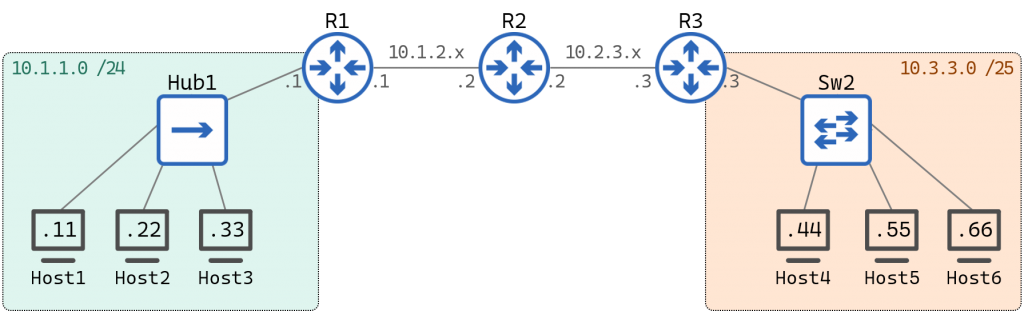
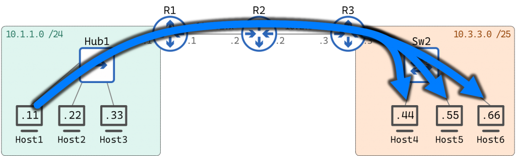
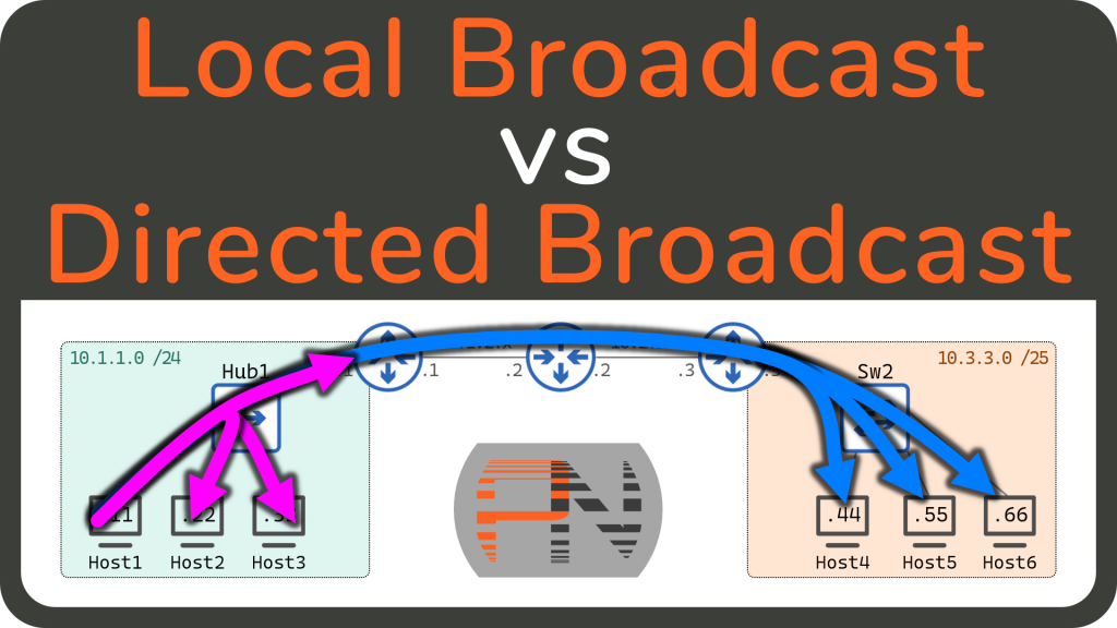
We’re going to use this topology to talk through these concepts:
To start, we must define the term “Broadcast.” A Broadcast is any frame or packet that is meant to be delivered to everyone on the local network.
A broadcast is roughly the opposite of a Unicast message. Which would be a communication from one host to another single host. Unicast is sometimes referred to as one-to-one communication, whereas Broadcast could be considered one-to-all communication.
The definition of a Broadcast mentioned frame and packet — this is because there are Layer 2 and Layer 3 aspects to the term Broadcast.
Layer 2 Broadcasts
A Layer 2 Broadcast is any frame with a Destination MAC address of FFFF.FFFF.FFFF.
This is a MAC address specifically reserved for Broadcast Frames. It is also sometimes displayed as ff:ff:ff:ff:ff:ff or ff-ff-ff-ff-ff-ff — these are all identical ways of displaying the “all F’s” MAC address.
Any node on any network can simply create a L2 header with this destination MAC address in order to send a frame to everyone on the local network.
Switches know that if they see this destination MAC address they should automatically flood the frame out all interfaces (except the one it was received on).
Keep in mind, it is the sender of the frame that sets the Destination MAC address. Therefore, it is the sender of the frame that determines whether a particular frame will be delivered to everyone on the local network or to a single node on the network.
Layer 3 Broadcasts
Similar to a L2 broadcast, a Layer 3 broadcast is simply a special IP address set as the Destination IP address for a particular packet.
Unlike L2 broadcasts, however, there are two different options for what you use as the Destination IP address for a Layer 3 Broadcast.
Those two options are the Local Broadcast and the Directed Broadcast (which is also sometimes called the Targeted Broadcast).
Local Broadcast
The Local Broadcast IP address is 255.255.255.255.
Whatever IP network a particular host is on, that host can always use this IP address to send a packet to every node on the Local Network.
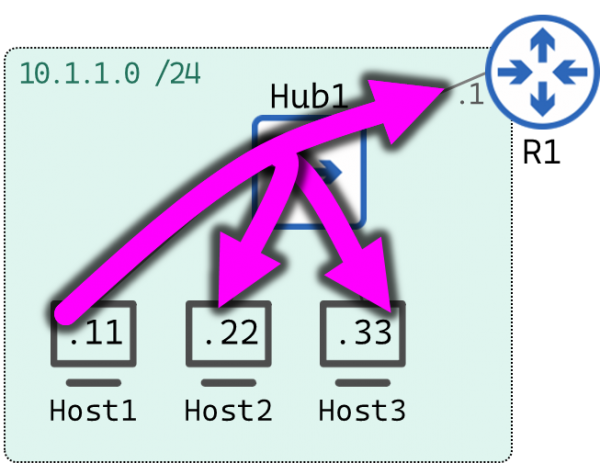
In our topology, Host 1 could send a message to the IP address 255.255.255.255 to speak to everyone else on it’s own local network.
Notice this also includes the Router. Since the R1 has an IP address in the 10.1.1.0/24 network, it is a member of Host 1’s local network.
Host1# ping 255.255.255.255
PING 255.255.255.255 (255.255.255.255): 56 data bytes
64 bytes from 10.1.1.11: seq=0 ttl=64 time=0.044 ms
64 bytes from 10.1.1.33: seq=0 ttl=64 time=0.944 ms (DUP!)
64 bytes from 10.1.1.22: seq=0 ttl=64 time=1.108 ms (DUP!)
64 bytes from 10.1.1.1: seq=0 ttl=255 time=1.324 ms (DUP!)
^C
--- 255.255.255.255 ping statistics ---
1 packets transmitted, 1 packets received, 3 duplicates, 0% packet loss
round-trip min/avg/max = 0.044/0.855/1.324 ms
Host1#
Host 1 sent a ping to 255.255.255.255 and received responses from itself (10.1.1.11), Host 3 (10.1.1.33), and Host 2 (10.1.1.22), and the Router (10.1.1.1).
This is what the packets looked like on the wire:
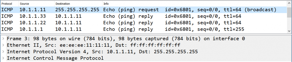
Notice the Destination IP address is 255.255.255.255. Notice also the Destination MAC address is ff:ff:ff:ff:ff:ff. Which makes this packet both a L2 broadcast and a L3 broadcast.
In the packet capture window, we can see the responses from Host 3, Host 2, and the Router. But we don’t see the response form Host 1 — that packet was simply sent internally and never actually reached the wire.
Moreover, notice Wireshark correctly labeled that packet as a broadcast packet — again, anything sent to 255.255.255.255 is a Broadcast.
For the sake of comparison, here is a packet capture of a Unicast ping between Host 1 and Host 3:
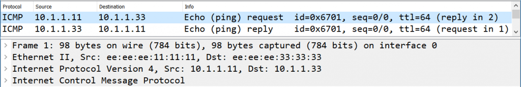
Notice the L2 source and destination are the MAC addresses which belong to Host 1 (ee:ee:ee:11:11:11) and Host 3 (ee:ee:ee:33:33:33). And of course the L3 source and destination are the IP addresses which belong to Host 1 (10.1.1.11) and Host 3 (10.1.1.33).
Directed Broadcast

The Directed Broadcast IP address is what is known as the Broadcast IP for each Subnet. To find this IP address, you will have to do a little subnetting.
Much like the Local Broadcast described above, the Directed Broadcast IP can be used by any host to speak to every host on it’s own local network.
Host 1 has the IP address 10.1.1.11 on the 10.1.1.0/24 network. The Broadcast IP address of this IP subnet is therefore 10.1.1.255.
Host 1 can use this IP address to send a message to everyone else on it’s own local network — just like it did with the Local Broadcast above:
Host1# ping 10.1.1.255
PING 10.1.1.255 (10.1.1.255): 56 data bytes
64 bytes from 10.1.1.11: seq=0 ttl=64 time=0.046 ms
64 bytes from 10.1.1.33: seq=0 ttl=64 time=0.615 ms (DUP!)
64 bytes from 10.1.1.22: seq=0 ttl=64 time=0.835 ms (DUP!)
64 bytes from 10.1.1.1: seq=0 ttl=255 time=1.261 ms (DUP!)
^C
--- 10.1.1.255 ping statistics ---
1 packets transmitted, 1 packets received, 3 duplicates, 0% packet loss
round-trip min/avg/max = 0.046/0.689/1.261 ms
Host1#
Host 1 sent a ping to 10.1.1.255 and received responses from itself (10.1.1.11), Host 3 (10.1.1.33), Host 2 (10.1.1.22), and the Router (10.1.1.1).
This is what the packets looked like on the wire:

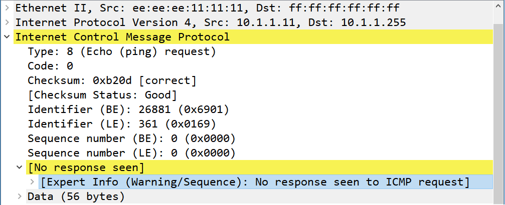
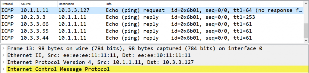
Notice the destination IP address is 10.1.1.255, and the Destination MAC address is ff:ff:ff:ff:ff:ff.
Wireshark’s analysis of these packets reveal two interesting details:
First, you and I both know that 10.1.1.255 is the Broadcast IP for the 10.1.1.0/24 network. But Wireshark failed to mark it as such as it did for the Local Broadcast in the prior example.
The reason is that Wireshark doesn’t know that this capture is from a network with a /24 mask. Therefore, Wireshark cannot infer that 10.1.1.255 is a Broadcast IP. If the mask were /22, the Broadcast IP would be 10.1.3.255, and the IP 10.1.1.255 would be a perfectly valid host address.
Second, notice the yellow background on the ICMP header. This is Wireshark indicating the “expert info” issued a warning because no response was found for the ICMP echo request.
Wireshark saw an echo request sent to 10.1.1.255, and was therefore looking for a response from 10.1.1.255. Which you and I both know is not an actual host that could have responded.
At this point we’ve proven that a host can use either the Local Boadcast IP or the Directed Broadcast IP to speak to every node on it’s local network.
Which begs the question. If both of these types of broadcast perform the same function, why do we have two different types of L3 broadcasts?
The answer: The Directed Broadcast can do something that the Local Broadcast cannot. The Directed Broadcast can be used to speak to every node on a foreign network.
Directed Broadcast to a Foreign Network
Every IP network has its own Broadcast IP. Therefore, Hosts can use the broadcast IP address of a foreign network to direct a broadcast to every node in that foreign network. Hence, the term directed broadcast (or sometimes targeted broadcast).
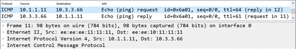
In our topology, Host 1 can use the IP address 10.3.3.127 to speak to every host in the 10.3.3.0/25 network:
For comparison purposes, I want to first show you a Unicast ping from Host 1 to Host 6.
Host1# ping 10.3.3.66
PING 10.3.3.66 (10.3.3.66): 56 data bytes
64 bytes from 10.3.3.66: seq=0 ttl=61 time=3.792 ms
^C
--- 10.3.3.66 ping statistics ---
1 packets transmitted, 1 packets received, 0% packet loss
round-trip min/avg/max = 3.792/3.792/3.792 ms
On the wire, this is what was captured between Hub1 and R1:
The Source IP is 10.1.1.11 (Host 1) and the Destination IP is 10.3.3.66 (Host 6). This is the L3 header, and for the most part will remain unchanged throughout the entire trip.
The L2 header as it leaves Host 1 has the Source MAC address of ee:ee:ee:11:11:11 (Host 1) and a Destination MAC address of ee:ee:10:11:11:11 (R1). This L2 header will be discarded and regenerated every hop along the path.
This same packet captured between R3 and SW2 looks like this:
Notice the L3 header is unchanged. But the L2 header now includes a Source MAC of ee:ee:10:33:33:33 (R3) and a Destination MAC of ee:ee:ee:66:66:66 (Host 6).
Now let’s test the Directed Broadcast to a foreign network. We’ll have Host 1 ping the IP address 10.3.3.127. Remember there are four nodes on the 10.3.3.0/25 network and we should expect a response from each of them.
Host1# ping 10.3.3.127
PING 10.3.3.127 (10.3.3.127): 56 data bytes
64 bytes from 10.2.3.3: seq=0 ttl=253 time=1.171 ms
64 bytes from 10.3.3.66: seq=0 ttl=61 time=3.683 ms (DUP!)
64 bytes from 10.3.3.55: seq=0 ttl=61 time=7.340 ms (DUP!)
64 bytes from 10.3.3.44: seq=0 ttl=61 time=9.838 ms (DUP!)
^C
--- 10.3.3.127 ping statistics ---
1 packets transmitted, 1 packets received, 3 duplicates, 0% packet loss
round-trip min/avg/max = 1.171/5.508/9.838 ms
As expected, we received four responses to our ping: Router 3 (10.2.3.3), Host 6 (10.3.3.66), Host 5 (10.3.3.55), and Host 4 (10.3.3.44).
Oddly, R3 responded from the IP address 10.2.3.3 — R3’s IP address on the link between R2 and R3. I would have expected this response to come from the IP address 10.3.3.3. I am unsure if it’s a bug or intended behavior or merely Cisco’s implementation of responding to Directed Broadcasts. Either way, this response is indeed from R3.
The packets on the wire reveal some interesting details. Here is the capture on the link between Hub1 and R1:
The most significant fact to point out is this packet is a unicast packet. Notice the L2 and L3 headers are constructed identical to the unicast ping between Host1 and Host6 (except the destination IP address, of course).
This highlights an important fact: Host 1 does not know it is speaking to a directed broadcast IP address. You and I know, because we can see the topology map; but from Host 1’s perspective, 10.3.3.127 is merely an IP address on a foreign network. Host 1 is simply following all the regular rules for speaking to an IP on a foreign network.
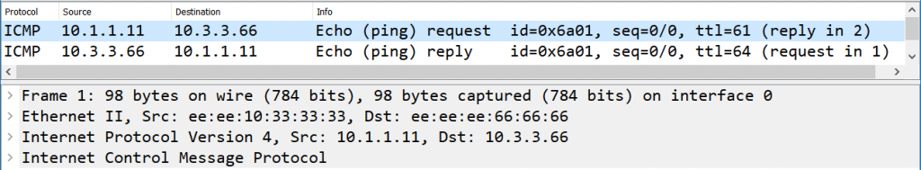
In fact, the packet travels from Host1 to R1, and from R1 to R2, and from R2 to R3 as a regular unicast packet. The only Router that knows that the IP address 10.3.3.127 is the broadcast IP for the destination subnet is R3. And the capture on the other side of R3 reveals what R3 does with the unicast packet it received:

Notice the destination MAC address is ff:ff:ff:ff:ff:ff, and the Destination IP address is 255.255.255.255. This is now a L2 and L3 Broadcast.
R3, knowing that this packet was sent to a Directed Broadcast IP address, translated the unicast packet it received into a broadcast packet. This is how the single Unicast packet sent by Host 1 was delivered to everyone on the 10.3.3.0/25 network.
Security
While the functionality of sending a packet to every host on a foreign network seems pretty neat. In practice, this is generally regarded as a security risk.
Directed broadcasts were invented at the dawn of computer networking, when the Internet was a much friendlier place. Back then it was simple enough to simply trust the other users on the Internet not to abuse the Directed broadcast.
However, as the Internet grew, that inherit trust of the other users went away. Currently nearly every modern operating system and router software ignore directed broadcasts.
In order to build the lab we used in this article, I had to explicitly enable responding to and processing Directed Broadcasts on the Router and the Linux hosts.
On a Cisco Router, that involved this command:
R3#  show run int eth0/0
!
interface Ethernet0/0
 mac-address eeee.1033.3333
 ip address 10.3.3.3 255.255.255.128
 ip directed-broadcast
On a Linux host, that involved changing the value of this file from 1 to 0:
Host1# cat /proc/sys/net/ipv4/icmp_echo_ignore_broadcasts
0
I say all this because inevitably after reading this article some of you will try to ping a foreign network’s broadcast IP, and it will likely fail.
Which makes sense if you put yourself in the Network Administrator’s shoes. You wouldn’t want some random user on the Internet to be able to send a ping to every host on your network.
Summary
In this article we discussed the ideas of a Layer 2 Broadcast and a Layer 3 broadcast. We further unpacked the L3 broadcast as we dove into the concepts of the Local Broadcast and the Directed Broadcast (also called the Targeted Broadcast). To summarize those definitions:
- Local Broadcast IP –
255.255.255.255- Can be used to speak to everyone on the Local network
- Directed Broadcast –
<Broadcast IP of each Subnet>- Can be used to speak to everyone on the Local network
- Can be used to speak to everyone on a Foreign network
Throughout this article we showed you screen shots from the packet captures from testing the Local Broadcast and the Directed Broadcast. If you’d like to download the capture files and study them yourself, you can do so here:
Moreover, if you prefer learning this content via videos, I present two Youtube video options for you:
This video is a quicker run through of just the concepts and tests from this article. In this video we’ll define Local and Directed broadcasts, then do some ping tests to prove they work as described.
This video covers the same concepts but is a bit more thorough and digs into the packet captures. We’ll define Local and Directed broadcasts, then run some ping tests to prove their operation. But we’ll also look at the Packets on the wire and talk through what is going (much like we did in this article).


Hi, I don’t undertand how you can ping an other network having an IP of 10.x.x.x. I thought those prive address ranges were not routable and your router would drop them immediately. Can you help me with it? I think I might misunderstand something about that picture above. Thanks.
Private addresses are indeed Routeable… they simply aren’t routeable on the Internet. Within this lab topology, however, nothing prevents private IP addresses from talking to private IP addresses.
Hello.
Why wouldn’t private addresses be routable within the internal environment, like within the company’s own network (aka the enterprise network)? Please correct me if I’m wrong, but if a router has an entry in its routing table, then it will route the packet according to the information it has in its routing table. Otherwise, how would internal routing protocols work?
Correct!
Awesomely explained!!
You are the best and your explanation is sharp.
Very very good article..
Thank you!
Awesome! mate
Do you know something?
That was the answer that I was looking for.
I feel elated after reading your article.
Much appreciated!
Glad this helped, Ismael =). You’re very welcome.
one typo, “…flood the flame out…” I chuckled when I read it.
oops! ha, good catch. Fixed it =)
thanks ED for your all efforts,
Its really helpful But I am trying to replicate this lab on windows 10 and gns3 vpc is not responding to local BD 255.255.255.255 showing that cant resolved this address.How could it be resolved.
Hi there Ed thanks for the article , im having the same issue with faiza , do you know what can we do to check on that? also would it possible for you to share the gns3 lab that you have in your guide here? Thanks.
Hi there Ed thanks for the article , im having the same issue with faiza , do you know what can we do to check on that? also would it possible for you to share the gns3 lab that you have in your guide here? Thanks
When R3 generates the return packet it does a routing lookup back to the source and generates the packet sourced from the outgoing interface. The 10.2.3.3 address in this case.
This is also why you typically need to specify source interfaces for SNMP, syslog, ntp etc if you want the router to use a consistent address.
Ed, your articles always amaze me. They are not ordinarily laid out like with other books. You go into the details explaining them bit-by-bit with drawings and examples. You are always bookmarked in my Favorites.
I really enjoyed reading your comparison of local broadcast vs. directed broadcast! It’s fascinating to see how these concepts play such a crucial role in networking and gaming environments. The clarity you provided on the advantages of each type was super helpful, especially for someone looking to enhance their understanding of network traffic. Do you think one method is more effective than the other in real-time gaming scenarios? Thanks again for such an insightful geometry dash wave post!
Growing reliance on the Internet has changed the original trust model between users and networks, especially as legacy mechanisms like directed broadcasts are increasingly disabled by modern systems. Network hardening and router-level filtering can sometimes create unexpected connectivity issues, where users may benefit from guidance such as LifeSaver customer service when troubleshooting configuration or access problems.