When connecting two sites together using a Virtual Private Network (VPN), a common issue that is encountered is trying to build a VPN with overlapping networks — where both sites happen to use the same Private IP addresses.
In such cases, hosts on one side of the VPN tunnel will be unable to communicate with the hosts on the other.
The problem can be circumvented, however, with clever use of Network Address Translation.
VPN Overlapping Networks: The Problem
In the example below, there are two sites – Seattle and Denver – connected with a VPN tunnel between R1 and R2. Both Seattle and Denver are using 10.0.0.0/24 for their internal network.
Host A in Seattle (10.0.0.77) needs to speak to Host D in Denver (10.0.0.88).
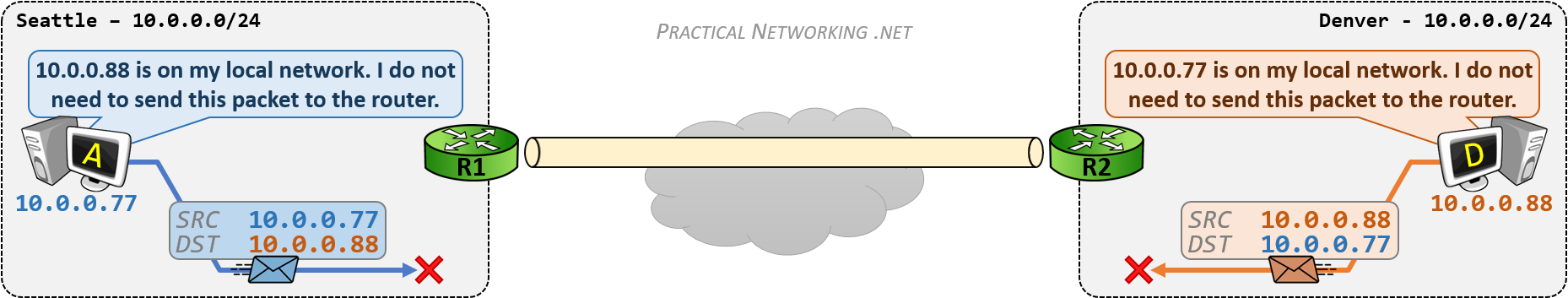
Since Host A is configured with the IP 10.0.0.77/24, Host A believes that every IP address in the range of 10.0.0.0 – 10.0.0.255 exists on its own local network in Seattle. Therefore, if Host A attempts to send a packet to 10.0.0.88, it will not send the packet to the Router.
Host D will have the same problem, Host D is configured with the IP 10.0.0.88/24 and also believes that the range 10.0.0.0 – 10.0.0.255 exists on its own local network in Denver. Therefore, any packet Host D sends to the IP 10.0.0.77 will be sent to the local network, and not to the Router.
If the packets are not sent to the Router, then the Routers are unable to forward them through the VPN tunnel to the other side. As a result, because of the overlapping networks, neither side will be able to speak to the other.
VPN Overlapping Networks: The Solution
The solution to the problem is to convince each host that the other host is on a foreign network. That would cause them to send packets to the Router, which can then send them through the VPN tunnel.
This will be attained by making the Seattle network appear as 10.1.1.0/24 when speaking to Denver, and making the Denver network appear as 10.2.2.0/24 when speaking to Seattle.
There are two ways of deploying Network Address Translation to facilitate this solution, one involves a NAT configuration on both routers, the other a NAT configuration on one router.
This article uses Routers as the device’s performing NAT. Many other devices can also perform NAT and the concepts described will still apply.
Solution #1 – Policy NAT on Both Sides
The first solution involves using Policy NAT on both routers to mask their internal network when speaking to the opposite side. Recall that a Policy NAT is a type of NAT that involves making a translation decision based upon matching both the source and destination address.
R1’s Policy NAT configuration will match packets with a Source IP of 10.0.0.0/24 (Seattle’s actual network) and a Destination IP of 10.2.2.0/24 (Denver’s masked network), and translate the Source IP to the 10.1.1.0/24 network (Seattle’s masked network).
R2’s Policy NAT configuration will match packets with a Source IP of 10.0.0.0/24 (Denver’s actual network) and a Destination IP of 10.1.1.0/24 (Seattle’s masked network), and translate the Source IP to the 10.2.2.0/24 network (Denver’s masked network).
In this way, R1 is masking the Seattle 10.0.0.0/24 network as 10.1.1.0/24, and R2 is masking the Denver 10.0.0.0/24 network as 10.2.2.0/24.
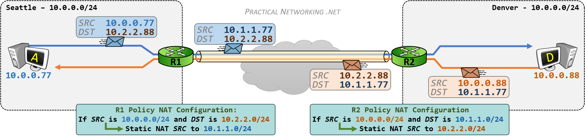
When Host A sends a packet to Host D, the source IP will be 10.0.0.77 and the destination IP will be 10.2.2.88 – an IP address in a foreign network. Host A will send this packet to R1, who will change the Source IP to 10.1.1.77 in accordance with R1’s Policy NAT configuration.
The same will occur when Host D sends a packet to Host A – the packet will have a source of 10.0.0.88 and a destination of 10.1.1.77. This packet will be sent to R2, who will translate the source IP to 10.2.2.88.
Inside the VPN tunnel, the packets will be appear as if the 10.1.1.x network is speaking to the 10.2.2.x network.
When each hosts’ packet arrives at the opposite router, the router will un-translate the destination address back to the appropriate IP address:
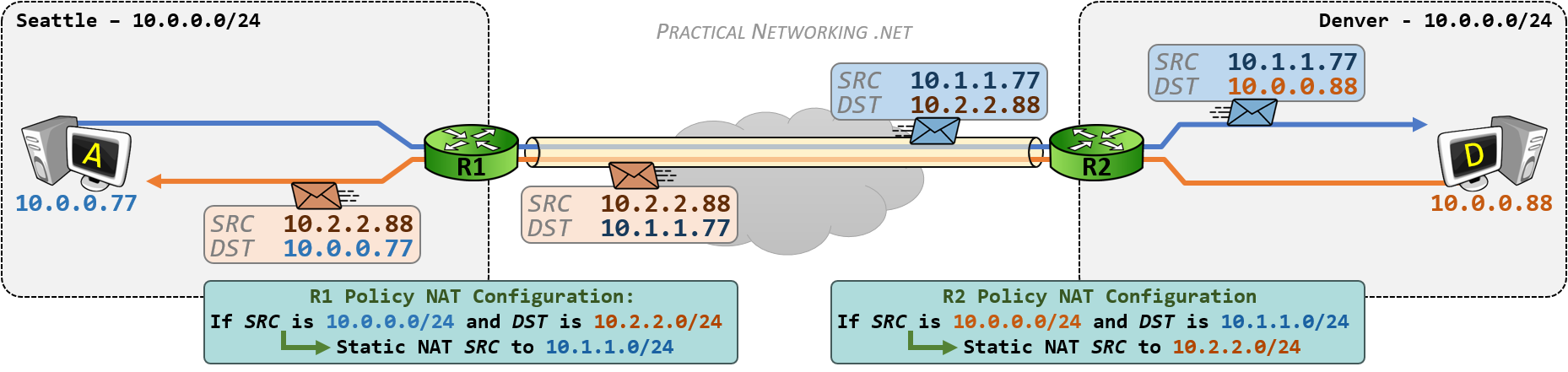
R2 will un-translate the destination IP of the blue packet from 10.2.2.88 to 10.0.0.88 and send the packet to Host D.
R1 will un-translate the destination IP of the red packet from 10.1.1.77 to 10.0.0.77 and send the packet to Host A.
This will enable hosts in Seattle and hosts in Denver to speak to each other, despite both sites having IP addresses in overlapping networks.
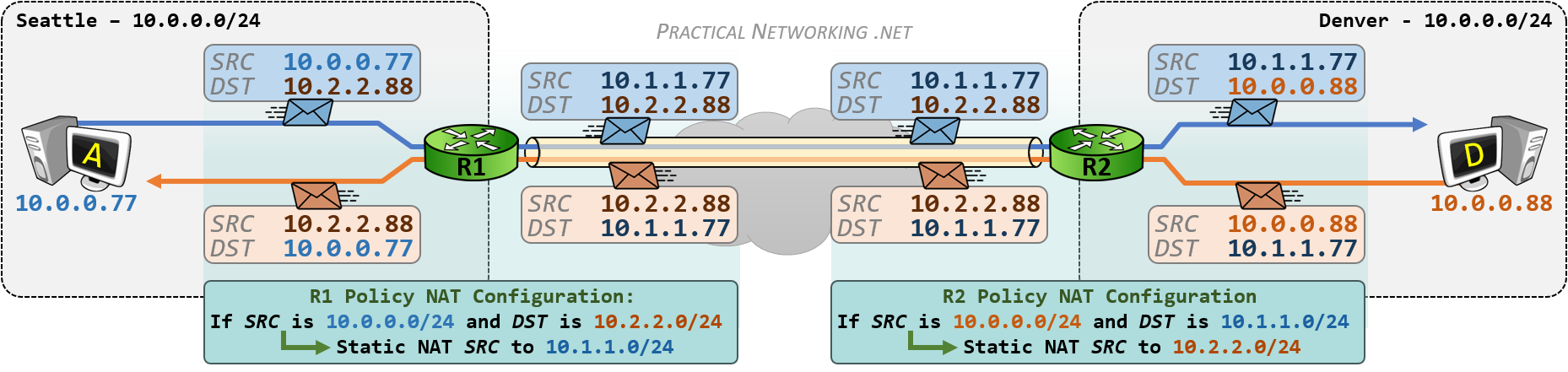
The whole process can be seen in the illustration below. This is, essentially, a combination of both images above, with the translations each router is responsible for highlighted:
Solution #2 – Policy Twice NAT on One side
Solution #1 requires both Routers to configure a Policy NAT. However, there are times when the NAT Device on one side does not support a Policy NAT configuration. In those cases, all the address translation will have to occur on a single device. Which brings us to Solution #2.
Solution #2 will still involve a Policy NAT – making a NAT decision based upon the Source and Destination. In addition, Solution #2 will also involve a Twice NAT – translating both the Source and Destination. Combined, Solution #2 will require Policy Twice NAT configuration.
Solution #2 will still solve the overlapping networks problem in the same way – by convincing the local site that the opposite site is on a foreign network. The only difference is Solution #2 will attain this effect by deploying address translation on only one router.
Once again, the goal will be to make the Seattle network appear as 10.1.1.0/24 when speaking to Denver, and make the Denver network appear as 10.2.2.0/24 when speaking to Seattle.
Since Host A (in Seattle) considers Denver as 10.2.2.0/24, R1 must be configured with a Policy NAT that matches traffic with a Source of 10.0.0.0/24 and a destination of 10.2.2.0/24.
For matched traffic, the source will be translated from 10.0.0.0/24 to 10.1.1.0/24 (making Seattle appear as the 10.1.1.0/24 network). Additionally, the destination will be translated from 10.2.2.0/24 to 10.0.0.0/24 (to allow the packet’s to be successfully delivered to Denver’s true network).
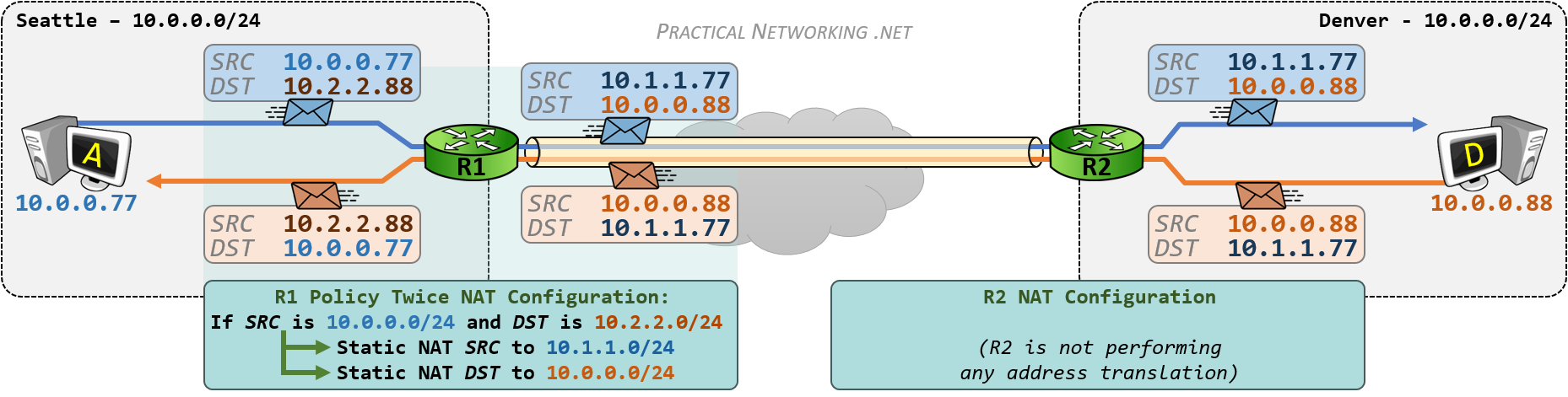
On the way back, when Host D is responding, the packet will have a source of 10.0.0.88 and a destination of 10.1.1.77. The packet will be sent to R2, which will forward it through the VPN tunnel. Upon arriving at R1, R1 will un-translate the packet:
The source IP of 10.0.0.88 will be translated to 10.2.2.88 (making Denver appear as the 10.2.2.0/24 network), and the destination IP of 10.1.1.77 will be translated to 10.0.0.77 (to allow the response packet to be successfully delivered to Seattle’s true network).
In this way, we can use a single Policy Twice NAT on one side of the VPN tunnel to mimic the behavior of using a Policy NAT on both sides outlined in Solution #1.
Summary
In the end, both solutions above accomplished the same goal: they made it seem like the IP networks on either side of the VPN tunnel were unique, and did not overlap.
Of course, the ideal situation would be for both sides of the VPN tunnel to actually have unique IP networks. But failing that, the solutions above provide a practical work around.
Comparing the two solutions, Solution #1 is cleaner, and most likely to lend itself to simpler troubleshooting and debugging in the future. Both sides of the VPN tunnel are equally contributing to the overall solution.
Solution #2, while viable, should be reserved only for cases where both sides are unable to or unwilling to configure a Policy NAT.
Either way, solving the problem of overlapping networks on a VPN simply involves using two tools in the Network Address Translation arsenal: Policy NAT and Twice NAT.


Hello Ed,
Thank you for the excellent explanation on how to solve an issue like this. I have included an example of how your Solution #2 would look on a Cisco device. Is this correct?
SeattleInside
subnet 10.0.0.0/24
Seatle2Denver
subnet 10.1.1.0/24
ToDenver
subnet 10.2.2.0/24
DenverInisde
subnet 10.0.0.0/24
nat (inside,outside) source static SeattleInside Seatle2Denver destination static ToDenver DenverInisde
Thanks again!!
Yeap, looks right to me! You’re configuring a Policy, Twice NAT on a Cisco ASA running 8.4+ code.
Hej Ed,
You are gem in explaining and depicting the network diagrams to clearly focus on the subject, there is always a pleasure reading your posts. Thumps Up!
A gentle request to add the NAT configurations further emphasis the understanding this concept.
Cheers, Tech Kludge
Hi techkludge,
I wanted this article to apply to all vendors, so opted intentionally to avoid any specific configuration.
Hopefully though, there is enough details in the article and in this Cisco ASA NAT configuration guide or Cisco IOS Router NAT configuration guide that readers can put together the relevant NAT commands themselves. =)
Thank you for the kind words.
Good work.
May I know which tool do you use for drawing those topology diagrams?
Hi Jai, Thank you! I use PowerPoint for all my illustrations. It isn’t the best tool, but I’ve gotten pretty accustomed to using it.
Hi Ed,
Your websirte is a treasure for me. Thanks for the great explanations.
I do understand the whole NAT-ting process, However I still don’t get how does the computers in seattle know that they should use the 10.2.2.0/24 to reach Denver (and vice versa) ?
Is this achieved through a DNS manipulation ?
Thanks,
Hi Ibrahima, glad you enjoyed the content =).
That part is somewhat abstracted from this process. Maybe it’s DNS. Maybe it’s the users in Seattle manually typing “ping 10.2.2.x” (or SSH, or RDP, or etc…). Maybe it’s something else. One way or another, the NAT configurations above would simply enable connectivity between the IP subnets. How the user utilizes that connectivity is an entirely different problem to solve.
Hope this helps =)
Hello Ed,
Thank your very much for your article. However I’m not quite sure to understand this part in the #1 solution :
R2 will un-translate the destination IP of the blue packet from 10.2.2.88 to 10.0.0.88 and send the packet to Host D.
How the router is able to know that the destination adress must be translated ? It only has a Nat rule to translate the source adresse no ?
Thanks for you help.
FXG
Hi FXG. Glad you liked the article.
The NAT configuration on R2 does this:
Notice the configuration translates the source of outbound packets, from 10.0.0.0/24 to 10.2.2.0/24.
For inbound packets, the reverse happens: the destination is translated from 10.2.2.0/24 back to 10.0.0.0/24, hence — untranslated from the outbound translation.
Remember, Static NAT is Bidirectional, which means even if the packet wasn’t initiated from an internal host, the “un-translation” will still occur.
Hello,
great article. How does the routing work ? If I ping a remote address that overlaps with a local address, the router will never know it is a remote address, unless you ping the DNS name associated with the other side, is that the right assumption to make
Hi Georg. That is exactly why you need to mask the other side to so it appears as a different network to the local side. In each example above, Seattle thinks Denver is the 10.2.2.0/24 network, even though Denver is actually the 10.0.0.0/24 network.
Best ever explanation on vpn concept with NAT. Thank you for your effort on emphasizing on each and every major point.
Thank you for the kind words, Richa =)
Hi, thanks for this guidance.
But can you please fix my problem in my network, i try my best to explain it to you.
Main Office with 1 ip Public to mikrotik that have local ip 10.1.10.0/23
second Office with IPsec VPN with local ip 172.23.133.0/29
i can ping to second Office without any problem prom all local ip Main Office 10.1.10.2-10.1.11.255
here is the problem:
since now we have situation (COVID19)
half my people working from home using their home internet.
some of those need to access Second Office local network ip 172.23.133.0/29
so i try to setup new VPN connection for those peoples.
1st i try PPTP (172.2.2.0/24) directly to my mikrotik, the result is i only able to ping my VPN gateway 172.2.2.1, cant ping my main mikrotik gateway 10.1.10.1 (from 10.1.10.0/23) also cant ping to Second Office ip 172.23.133.0/29
2nd i try using OpenVPN also directly to my mikrotik with all the certificate and user. But i have same result, cant ping my main mikrotik gateway 10.1.10.1 (from 10.1.10.0/23) also cant ping to Second Office ip 172.23.133.0/29.
i already try to create NAT but still no clue whats happend.
sorry for my bad english.
and Thank you in advance for the help.
cheers
This doesn’t sound like an Overlapping Networks problem. Sounds like a Hairpinning and VPN problem. I’d encourage you to contact your support vendor or use public help forums like Reddit or Spiceworks.
Good article. helped me a lot. I have one question though . I am assuming but wanted to confirm.
So when traffic sourced out of Seattle with Src ip of 10.2.2.88. I am assuming Seattle network will somehow advertise that src subnet within Seattle network may be a null route and redistribute internally with igp or ibgp etc. So the return traffic is delivered back to this Seattle headend router?
Yes. The Routers in Seattle will have to know about and advertise knowledge of the 10.2.2.x network. Once the traffic gets to the Headend/VPN Router, it can do the NAT necessary to get it to Denver.
In both the case, what will be the VPN Encryption Domain ACL/ Intresting traffic ACL through the VPN is ???
It will be 10.1.1.x/24 and 10.2.2.x/24 on R1 and on R2 vice versa if im not wrong.
It’s going to differ for each device and vendor, some interpret the Encryption Domain (or Proxy IDs) before translation, and some do it after translation. So I can only speak to the devices I’ve had experience with, and for those devices the Encryption Domain will typically match the traffic as it appears inside the tunnel (10.1.1.0/24 <--> 10.2.2.0/24).
Hi This is very helpful. Can you elaborate if it is possible for the following scenario for the Solution #2?
Currently your example is using two /24 subnets to mask the source IP for both the West and East endpoints. The Seattle sees Denver as 10.2.2.x/24 and Denver sees Seattle as 10.1.1.x/24.
Can the same configuration for solution #2 be accomplished using a single shared /24 subnet? Or this is only possible to use two subnets?
Interesting question. Do you mean something like a dedicated subnet that always represents “the other side”. Meaning Seattle and Denver both see the other side as 10.3.3.0/24?
If so, the honest answer is I don’t know. I don’t think anything would stop you from configuring the NAT in that way, but I’m wondering if you’ll confuse the Router/Firewall, since now a single subnet exists in two locations?
This fine explanation for fine theory, thank you
I am trying to lab this example in GNS3 with R1 and R2 as IOSv Software (VIOS-ADVENTERPRISEK9-M), Version 15.6(1)T
and i dont succeed
Could you clarify with the NAT commands to help me
Regards
You’re welcome.
For NAT configuration instructions on Cisco Routers, I would point you to this article:
https://www.practicalnetworking.net/stand-alone/cisco-nat-configurations-ios-router/
Although, what you would need is instructions on a Policy NAT, which I’ve only published in my Cisco IOS NAT Course.
Thanks,
should i find in the course the configuration commands (with IOS) for this example ?
Regards
Yes. =)
Hi Ed,
Thank you for the explanation. I don’t understand one thing. I want to migrate VMs from Site A to Site B without changing any IP configurations on them. WHat will happen if I move the DC to Site B, how will the VMs from Site A communicate with it? As it is the same subnet…
Thank you!
By default they won’t. A computer will only send something to the Router/Default Gateway if what it’s trying to speak to is on a foreign network. That is why you need the address translation described above.
Thank you, so we are better off creating new network on one side and migrate all machines at once.
Hello, Great Explanation, very useful.
I have a question, for the masked networks we have to provide routing in routers right!! for the packet to be delivered to other side of the peer ??
Yes. Of course =)
Aoa,
I have two subnets both on same network (192.168.137.0/24) behind two ubuntu server devices. how I gave NAT to these devices to look that these subnets are on different networks.
My configuration is under:
(192.168.137.19)Client1—-(192.168.137.10)UbuntuServer(10.10.3.10)====(10.10.3.10)UbuntuS2(192.168.137.11)—-(192.168.137.20)Client2
UbuuntuS2 has IP of (10.10.3.11)
I’m not familiar with ubuntu NAT configuration. I’m afraid I can not help you. The article is meant to speak to the concepts, not the actual configuration.
Question, it seems this is happening between predeterminate locations…what about users trying to access a site from multiple locations, Is there any way to change the settings on their computers so they are able to login via VPN?, as I understand, NAT has to be configured from both sides, but I am talking about users at home. Its admirable that you reach the point to explain this process in such details. Your efforts are appreciated!
Often it’s easier to simply change the IP address assigned to VPN clients so it doesn’t overlap with their home network, or a foreign VPN network.
Can anyone show or know how to setup DNS for this configuration to get it to work?
What do you mean? Perhaps post the question on Discord: pracnet.net/discord
VxLAN is a best approach to this topology
Hello Ed Harmoush,
Is Solution #2 (Policy Twice NAT on One side) for overlapping networks is possible with Cisco CSR Router? if so could you please help me with sample commands.
I watched all your videos including Twice NAT on IOS router but couldn’t configure it. If you provider sample configuration based on above image that would be helpful.
Thank you!
Hi Ed,
Thanks for explaining the need of NAT in Site-to-Site VPN configuration. I have a situation where there might be a problem utilizing NAT for VPN configuration and I need your advise on that.
Taking reference from the example network used in blog, lets suppose both PC”A” and PC”D” wants to transfer data using some protocol where only their original IP address can be used (not the translated one) to address the Host. How in that scenario, they would be able to communicate?
They cannot.
IP was meant to uniquely identify every device on the Internet. RFC1918 allowed the re-use of IP space (10.x, for instance) which “broke” the original intent of IP that every device has a unique address. Hence, we play games with NAT to make it look like pcA and pcB are speaking to IP addresses in foreign networks.
Short of other such work arounds, two devices physically sitting in foreign networks, but sharing IP space cannot communicate.
Thanks Ed for the reply.
Let’s say PC”A” (eg. 192.168.0.77) and PC”B” (eg. 192.168.0.88) wants to communicate over VPN tunnel but they are sharing same subnet mask (255.255.255.0). In this case, is this possible to avoid NAT and use some other means to have communication?
try some vpn of this list https://vpnmag.ru/vpn-po-snizhennym-cenam/
Hello,
solution #1 is fine. But for solution #2 it is unlikely it will work.Or it will depend of the equipement behavior.
For the 1st outgoing packet, why R1 would send it towards R2 whereas it as the 10.0.0.0/24 network as directly connected network in its routing table ? It will go back to Seattle. Or maybe if the NAT is done after the routing it might get out (called server side NAT on some vendor).
Now for the VPN, you will have a policy encrypting traffic between 10.1.1.0/24 and 10.0.0.0/24, but your device must accept to have 10.0.0.0/24 defined as remote VPN network whereas it has it locally directly connected. It will aslo conflict with some vendors if you have other non NAT VPN on same device as 10.0.0.0/24 will be defined already as local VPN network and cannot be defined twice.
And for the return packet, if R1 is doing andispoofing, it will complain that it receives a 10.0.0.0/24 source on the external side as this is an internal network for him.
Jim
Managing VPNs with overlapping networks can become complex when routing conflicts, scalability, and secure connectivity all need to work together without interrupting performance. Cloud infrastructure and support responsiveness often play a major role in resolving these technical challenges, and https://cloud.pissedconsumer.com/customer-service.html is frequently referenced when discussing customer experiences with cloud-related services, troubleshooting efficiency, and platform reliability.